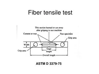
Download
1 / 24
240 likes | 423 Views
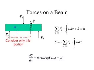
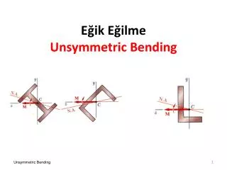
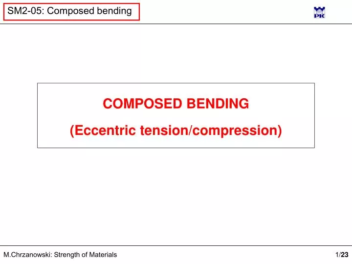
COMPOSED BENDING (Eccentric tension/compression). z. y. M y. Plane bending. Neutral axis for bending. z. x. z. y. + . Tension. Neutral axis for tension. Neutral axis for bending. z. x. - . z. y. M y. Combined bending. Plane bending. z. Neutral axis. z 0. =. +. +.

E N D
z y My Plane bending Neutral axis for bending z x
z y + Tension Neutral axis for tension Neutral axis for bending z x -
z y My Combined bending Plane bending z Neutral axis z0 = + + Neutral axis equation: „Eccentric” Squared inertia radius
N / A Bi-plane combined loading Normal stress Eccentrics Normal stress in terms of normal force and eccentrics y0 ,z0 Non-dimensional normal stress Normal stress at neutral axis Neutral axis equation
NEUTRAL AXIS MOVEMENT in (y,z) plane
Side view Stress distribution Cross-section view
+ N/A N N Neutral axis in an „infinity” A Side view Stress distribution Cross-section view
+ N/A N Neutral axis already being „seen” A Side view Stress distribution Cross-section view
+ N/A N Neutral axis outside of cross-section A Side view Stress distribution Cross-section view
+ N/A N Neutral axis touching cross-section contour N N A Side view Stress distribution Cross-section view
+ - N/A N Neutral axis within cross-section A Side view Stress distribution Cross-section view
Dual interpretation of neutral axis equation Eccentric co-ordinates Neutral axis co-ordinates
Dual interpretation of neutral axis equation 1. If neutral axis coincides with cross-section contour edge given by the equation: then from the transformed equation of neutral axis: one can find co-ordinates of normal force position (eccentricity):
Dual interpretation of neutral axis equation 2. If a number of neutral axis touches cross-section corner of given co-ordinates: then by inserting these co-ordinates into neutral axis equation one can obtain eqaution of a straigth line defining the position of a normal force:
2 cm 3 cm 3 cm 2 cm 8 cm 14 cm 4 cm 8 cm Example of cross-section kernel finding
a d C B D A b c Example of cross-section kernel finding z Mode 1: Finding eccentrties y 7,22 cm
e Example of cross-section kernel finding Mode 2: Finding normal force acting lines z E y 7,22 cm
f Example of cross-section kernel finding z Mode 2: Finding normal force acting lines F y 7,22 cm
g Example of cross-section kernel finding z Mode 2: Finding normal force acting lines y 7,22 cm G
Example of cross-section kernel finding z y 7,22 cm
Example of cross-section kernel finding z y 7,22 cm
Cross-section kernel Cross-section kernel defines normal force positions (eccentrities) such that resulting normal stress in the whole cross-section area has the same sign (plus for N>0 and minus dla N<0). Cross-section kernel has always a convex form.