Download

1 / 29
370 likes | 941 Views
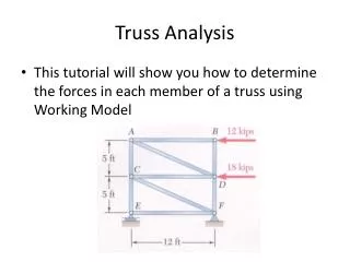
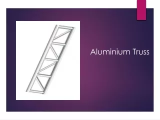
Calculating Truss Forces. Forces. Compression. A body being squeezed. Tension. A body being stretched. Truss. A truss is composed of slender members joined together at their end points. They are usually joined by welds or gusset plates. Simple Truss.

E N D
Forces Compression A body being squeezed Tension A body being stretched
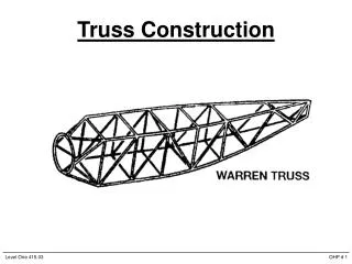
Truss A truss is composed of slender members joined together at their end points. • They are usually joined by welds or gusset plates.
Simple Truss A simple truss is composed of triangles, which will retain their shape even when removed from supports.
Pinned and Roller Supports A pinnedsupport can support a structure in two dimensions. A roller support can support a structure in only one dimension.
Solving Truss Forces Assumptions: All members are perfectly straight. All loads are applied at the joints. All joints are pinned and frictionless. Each member has no weight. Members can only experience tension or compression forces. What risks might these assumptions pose if we were designing an actual bridge?
Static Determinacy A statically determinate structure is one that can be mathematically solved. 2J = M + R J = Number of Joints M = Number of Members R = Number of Reactions
Statically Indeterminate B Each pin connection contributes TWO reaction forces A C D FD = 500 lb A truss is considered statically indeterminate when the static equilibrium equations are not sufficient to find the reactions on that structure. There are simply too many unknowns. 2J = M + R Try It 2(4) ≠ 5 + 4
Statically Determinate Is the truss statically determinate now? B A C D FD = 500 lb A truss is considered statically determinate when the static equilibrium equations can be used to find the reactions on that structure. 2J = M + R Try It 2(4) = 5 + 3
Static Determinacy Example Each side of the main street bridge in Brockport, NY has 19 joints, 35 members, and three reaction forces (pin and roller), making it a statically determinate truss. What if these numbers were different?
Equilibrium Equations The sum of the moments about a given point is zero.
Equilibrium Equations The sum of the forces in the x-direction is zero. Do you remember the Cartesian coordinate system? A vector that acts to the right is positive, and a vector that acts to the left is negative.
Equilibrium Equations The sum of the forces in the y-direction is zero. A vector that acts up is positive, and a vector that acts down is negative.
Using Moments to Find RCY A force that causes aclockwise moment isa negative moment. A force that causes acounterclockwisemoment ispositive moment. 3.0 ft 7.0 ft FDcontributes a negative moment because it causes a clockwise moment about A. RCy contributes a positive moment because it causes a counterclockwise moment around A.
Sum the y Forces to Find RAy We know two out of the three forces acting in the y-direction. By simply summing those forces together, we can find the unknown reaction at point A. Please note that a negative sign is in front of FD because the drawing shows the force as down.
Sum the x Forces to Find Ax Because joint A is pinned, it is capable of reacting to a force applied in the x-direction. However, since the only load applied to this truss (FD) has no x-component, RAx must be zero.
Method of Joints • Use cosine and sine to determine x and y vector components. • Assume all members to be in tension.A positive answer will mean the member is in tension, and a negative number will mean the member is in compression. • As forces are solved, update free body diagrams.Use correct magnitude and sense for subsequent joint free body diagrams.
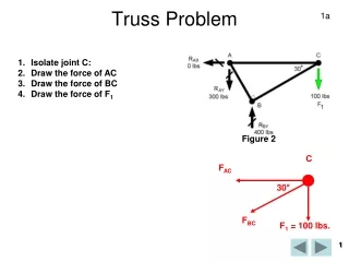
Method of Joints 4.0 ft Truss Dimensions B A C θ2 θ1 RAx D 3.0 ft 7.0 ft RAy RCy 500lb
Method of Joints 4.0 ft Using Truss Dimensions to Find Angles B 4.0 ft A C θ2 θ1 D 3.0 ft 7.0 ft
Method of Joints 4.0ft Using Truss Dimensions to Find Angles B 4.0 ft A C θ2 θ1 D 3.0 ft 7.0 ft
Method of Joints Draw a free body diagram of each pin. B A C 53.130° 29.745° RAx D RAy RCy 500lb Every member is assumed to be in tension. A positive answer indicates the member is in tension, and a negative answer indicates the member is in compression.
Method of Joints Where to Begin Choose the joint that has the least number of unknowns. Reaction forces at joints A and C are both good choices to begin our calculations. B AB BC BD A C CD AD RAx D 0 150lb 350lb 500lb RCy RAy
Method of Joints COMPRESSION
Method of Joints Update the all force diagrams based on AB being under compression. B AB BC BD A C CD AD RAx= 0 D RCy= 150lb 350lb RAy= 500lb
Method of Joints TENSION
Method of Joints COMPRESSION
Method of Joints Update the all force diagrams based on BC being under compression. B AB BC BD A C CD AD RAx= 0 D RCy= 150lb 350lb RAy= 500lb
Method of Joints TENSION
Method of Joints 500lb BD D TENSION 500lb