Download
1 / 34
340 likes | 419 Views
July 2010. Guidance for using the New LRE Bridge Component. Training Outline. Part 1 Cost-per –SF and Detailed Estimate Pay Item Detailed Estimate Segments Bridge Level Data Segment Level Data Supports Part 2 Sketches Supporting Tables and Other Information.

E N D
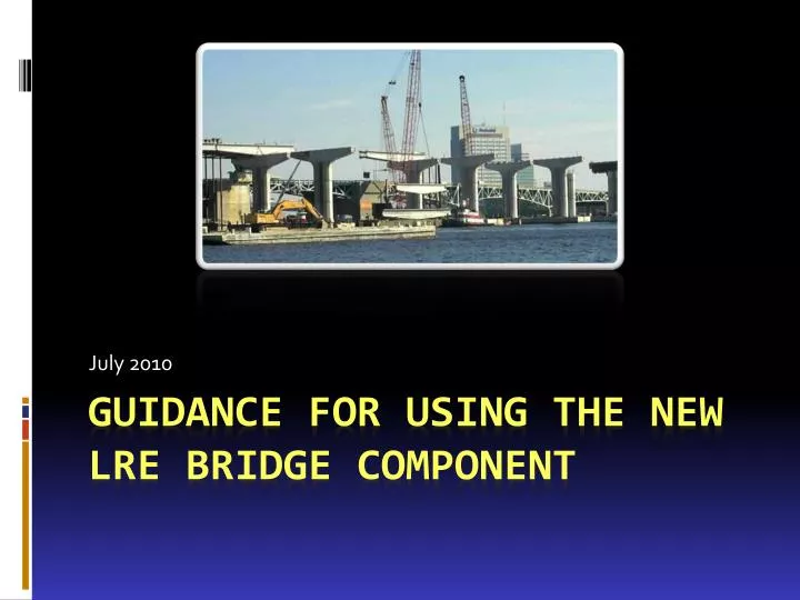
July 2010 Guidance for using the New LRE Bridge Component
Training Outline • Part 1 • Cost-per –SF and Detailed Estimate • Pay Item Detailed Estimate • Segments • Bridge Level Data • Segment Level Data • Supports • Part 2 • Sketches • Supporting Tables and Other Information
Cost-per-SF & Item Details • Two methods are now available for estimating bridges: • Cost-per-square foot (no change from previous) • Pay item detailed • You can choose to use either or both:
Primary Bridge Estimate • If you choose to have both a cost-per-square foot and a detailed estimate, you must designate one as the Primary: • For reporting and review (similar to Primary Version designation); • Not limited to LRE Coordinators; • Can be changed at any time (if the project is not in Blocked status).
Cost-per-Square Foot Method • The cost-per-square foot method will remain the same as it was previously. • Screen is the same, except the fields for Superstructure and Substructure types have been removed. • For projects that had bridges prior to the implementation of the detailed component, the implementation did not affect (or change) the existing costs-per-square foot.
The remainder of this presentation will apply to the Pay Item Detailed method of estimating bridges...
Pay Item Detailed Method • Designed for common bridge types (the “90%”) • Pay item detailed component is not intended for estimating “specialty” bridges • Specialty bridges can be estimated by the cost-per-square foot method, or as X-Items.
Bridge Segments • Bridges that havevarying types (or heights)can be separated intoSegments for moreaccurate estimating. • A bridge can have oneSegment, or many. • For each segment:Superstructure, Substructure and Foundation types are selected from a list.
First and Last Segments • When you initiate a detailed estimate, the system assumes there is one segment. • The first segment created is automatically designated as the “First” and “Last” segment: • End Bents are automatically added to the segments designated as “First” and “Last”.
Bridge Segments • If multiple segments are created, you must designate “First” and “Last” Segments so that end bent quantities will be appropriately generated:
Bridge Segments • Example of a bridge requiring multiple segments for variations in height:
Bridge Level and Segment Level Data • Data that remains consistent through all segments is input on the “Bridge Level” screen. • Bridge level data relates primarily to the type of construction and the characteristics of the bridge deck (typical section, railings, etc.). • Data that changes between segments is input on the “Segment Level” screen. • Segment Level data relates primarily to dimensions, and types for superstructure, substructure and foundation.
Bridge Level Data • User Input / Selection: • Bridge Typical Section • Construction Type • Average Skew Angle • Sidewalk Widths • Railings, Left & Right • Traffic Separator Width • Generated Values: • Total Cost and Cost/SF • Approach Slabs • Total Length and AverageWidth (from Segments) • Quantities for Displayed Pay items
New Bridge Defaults • When you create a newbridge a single segmentis created, with defaultmeasurements andcharacteristics. • The Bridge Level Detailscreen will display the InitialSegment Default values. • These values will not beaccurate for your bridge; • They are there because LREmust have a “starting point”; • You can change them here or on the Segment Details screen.
Segment Level Data • User Input, per Segment: • Segment Dimensions & Clearance • Over Land or Water • Number of IntermediateSupports • Superstructure, Substructure,Foundation Types (selected) • Calculated Values: • Average Pile Length • Span Length • Quantities for all relatedpay items
Segments & Intermediate Supports • The “Number of Intermediate Supports” is an input value on the segment, estimated by the coder. • There will be a default value for the first segment, based on total bridge length and other factors (bridge loads, etc.). The default value can be changed. • If additional segments are created, there will not be a default number of intermediate supports. The number will have to be estimated by the coder and manually entered. • This value has a significant impact on the quantities calculated!
Example of Segments and Supports • The example bridge below has been separated into 3 segments, for differing heights; • Intermediate Support numbers, per segment are: • Segment 1 = 0, Segment 2 = 2, Segment 3 = 0 • Don’t count end bents! (Automatically included.) These piers are counted as input values in Segment 2 The program automatically adds the quantities for this pier into Segment 3 The program automatically adds the quantities for this pier into Segment 2
Bridge Optional Tab • This tab contains input fields for several items that are commonly used on bridge projects, but do not have generated quantities. • Removal of Existing Structures • Sheet piling • Protection of Existing Structures • Navigation Lights, Fender System, Fiberglass Piles • Slope Protection • Expansion Joints • Takes the place of X-Items for these items. • Quantities must be included, but prices will be generated.
Bridge Widening Rules • The program requires that one of the widening types shown here be selected. • If the specific widening type falls outside of these options, the estimate should be based on the square foot cost or by using X-items.
Bridge Widening Rules • Widening Two Sides- The program is set up for widening on one side of the bridge. If the project requires widening on both sides, run as separate bridges and sum the quantities. • Match Existing - In general, the superstructure type of the bridge widening should always match the existing.
Typical Creek/Canal Crossings Flat Slab 18” Pile Bent Florida I- Beams 48” Dia. Drilled Shaft Bent
Typical Overpass Bridges Florida U-Beam Multi-column Pier Steel H-Piles Florida I-Beam Drilled Shaft Bent 48” Dia. Drilled Shafts Steel I-Beam Multi-Column Pier 18” Prestressed Piles
Multi Column Piers Multi-Column Piers Come in Different Shapes
Typical Overpass Bridges • Some overpass structures can be a long simple span (number of intermediate supports = 0). • Here is an example of a long steel plate girder overpass span:
Typical Interchange Ramps Steel Box Hammerhead 24” Prestressed Piles Steel I-Beam Hammerhead 24” Prestressed Piles
Hammerhead Piers Hammerhead Piers come in different shapes
Hammerhead Pier Options For high-level water crossings, two hammerhead piers set side-by-side may be a cost effective design solution given the wide bridge width. This can be approximated in the program by inputting one-half of the structure with a single hammerhead pier, then doubling the quantities. Short land piers are more likely to use multi column intermediate supports. The program assumes a single hammerhead pier for a given bridge cross section and limits the bridge width to less than or equal to 70 ft.
Span Length Guidelines * When the calculated average span length exceeds 130’, verify feasibility of hauling FIB to the bridge site.
Bridge Screens Flow • Bridges Tab • Bridge Summary Screen • Segments Tab • Bridge Level Detail Screen • Edit Detail Cost • Segments Summary • Edit Cost / SF • Optional Items Tab • Segment Detail • Optional Items Screen • Bridge $ / SF Screen • End(Back to Summary or Bridge Tab) • End(Back to Summary or Bridge Tab)