Download
1 / 14
140 likes | 385 Views
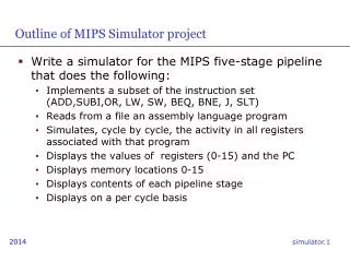
Outline of MIPS Simulator project. Write a simulator for the MIPS five-stage pipeline that does the following: Implements a subset of the instruction set (ADD,SUBI,OR, LW, SW, BEQ, BNE, J, SLT) Reads from a file an assembly language program

E N D
Outline of MIPS Simulator project • Write a simulator for the MIPS five-stage pipeline that does the following: • Implements a subset of the instruction set (ADD,SUBI,OR, LW, SW, BEQ, BNE, J, SLT) • Reads from a file an assembly language program • Simulates, cycle by cycle, the activity in all registers associated with that program • Displays the values of registers (0-15) and the PC • Displays memory locations 0-15 • Displays contents of each pipeline stage • Displays on a per cycle basis
Sample GUI – timing diagram – registers – memory – pipe stages
Type of Simulator: Architecture Simulator • Time-Driven Simulator: Has a central clock and moves from one clock cycle to the next, simulating all the activity of interest in that clock cycle.
Five-Stage Pipeline • IF Stage: Fetches instructions • If a conditional branch is encountered, use the predict not taken scheme explained in class • The IF stage places fetched instructions in an instruction queue, to be consumed by the ID stage. • Assume the PC has its own dedicated adder to increment the byte address by 4 (or word address by 1). • ID Stage: Decodes the instructions in the instruction queue, one by one. • Immediate operands are sign-extended to 32 bits • Makes operands available to the EX stage • Generates control signals
register forwarding, we need the new value for instruction 0 within the ALU phase of instruction 1.
Five-Stage Pipeline (contd.) • EX Stage: • Executes arithmetic/logical instructions • BEQ instructions are resolved in this stage • Check data dependencies and implement forwarding • MEM Stage: • Carries out access to the data memory • WB Stage: • Writes back into the register file (if necessary)
Parsing Instructions • The assembly language program must be read by the simulator • You can use a case statement associated with each possible instruction, which tells the simulator what to do with that instruction. • When an instruction reaches the ID stage, controls governing the rest of its activity will be generated.
A Straightforward Approach • Mimic within the simulator what happens in the MIPS pipeline • Generate the control signals associated with each instruction in the ID stage • Pass these signals along, stage by stage, along with the instruction. • check for data hazards • Every clock, mimic what is supposed to happen in each of the five stages and collect statistics on which stages are doing anything useful
Maintain Data Memory State • Keep track of the contents of the data memory • Assume the data memory size is 16 words • Assume the instruction memory size is 16 words • Data and instruction address spaces are separate
Instruction Memory & Register File • The program starts at location 0 of the instruction memory • The PC will point to this location at the beginning of the simulation • Each memory access takes 1 cycle • You can limit implementation to use registers 0-15
Simplifications • To make it easier for you to read in the assembly language program: • The assembly language use commas to separate operands; • No register names will be used: register numbers only. • Example: add 3 2 1 means add register 1 contents to those of register 2 and put the result in register 3. • Don’t use labels in your program: instead the beq instruction will identify its target by an offset. • Example: beq 4 5 -2 means that if the contents of registers 4 and 5 are identical, we branch to the instruction immediately preceding beq.
Reading the Assembly Language Program • C provides a number of ways in which to read input. For example, fscanf(fp, “%s %d %d %d”, opcode, &field2, &field3, &field4); where fp is a file pointer, opcode is a character array, and field2, field3, and field4 are integers
Parsing the Assembly Language Program • Some useful library functions (remember to #include <string.h>): • strcpy: Copies one string into another • strcmp: Compares two strings. Note that this will give you an output of 0 if the two strings match.
Simulator Output • The simulator must operate in single-step mode • Output consists of • Contents of each of the first 16 registers $1 to $15 and that of the PC (in decimal) • Output of data memory (0-15) • The number of clock cycles that have elapsed • Contents of each stage IF, ID, EX, MEM, WB.