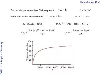
Download
1 / 43
430 likes | 588 Views
Modelling the melting behaviour of hyperstoichiometric uranium dioxide fuel. M. J. Welland, W. T. Thompson, B. J. Lewis Department of Chemistry and Chemical Engineering Royal Military College of Canada Kingston, Ontario International VERCORS seminar Gréoux les bains – France

E N D
Modelling the melting behaviour of hyperstoichiometric uranium dioxide fuel M. J. Welland, W. T. Thompson, B. J. Lewis Department of Chemistry and Chemical Engineering Royal Military College of Canada Kingston, Ontario International VERCORS seminar Gréoux les bains – France October 15-16, 2007
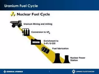
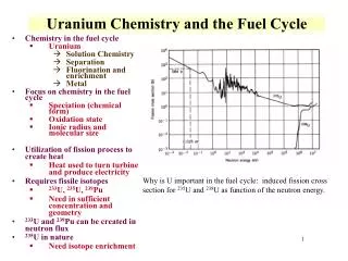
Outline • Impetus • Stoichiometric UO2 • Stefan model • Phase Field model, 1&2 dimensions • Non-stoichiometric UO2+x • Stefan model • Application to fission heating • Concluding remarks
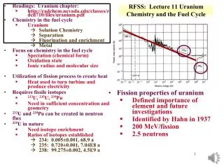
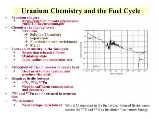
Defective Fuel Behaviour • Defects in the sheath can occur in < 0.1% of bundles • Coolant allowed to make contact with UO2 UO2+x • Fuel element performance degradation • Reduced gap heat transfer coefficient • Fuel oxidation • Reduced thermal conductivity • Lower incipient melting point Potential for centreline melting
U-O Phase Diagram UO2+x
Research Goals • Develop a model to describe centreline melting in operational, defective nuclear fuel elements • Canadian Nuclear Safety Commission: Generic Action Item (GAI 94G02) • Centreline melting in defective fuel? • Increase operating margins • Improve current safety analysis FFO-102-2 (67 kW/m, O/U = 2.16)
Stefan Model Derivation: UO2 • Heat balance in both phases and across interface • Solid-liquid interface moves with time • Implemented on a moving mesh
Phase Field Model • Stefan model cannot accommodate fission heating easily • Phase Field model is a more robust technique • Derived from first principles (Theory of Irreversible Processes) • More complicated to derive but easier and more versatile to implement • Uses same thermodynamic function as used to develop U-O phase diagram • Links thermodynamics with kinetics
Phase Field Model • Scalar field “φ” to represent phase transition • φ varies continuously between 0 and 1 (solid and liquid) General heat equation Stored heat Conduction Latent heat effects Heat source Phase field equation Rate of phase change Energy from phase change Interfacial energy effects Nucleation
Laser Flash Experiments • Heat deposited on surface • Good for determining material properties • Can be simulated with Stefan or Phase Field model D. Manara, C. Ronchi, M. Sheindlin, M. Lewis, M. Brykin, “Melting of stoichiometric and hyperstoichiometric uranium dioxide” J. Nucl. Mat. 342 (2005) 148
Model Comparison/Laser Flash Experiment: Thermogram for Stoichiometric Fuel 3120oK 1 2 3 4 Presented models use recently published material properties J.K. Fink “Thermophysical properties of uranium dioxide”, J. Nucl Mat. 279 (2000) 1
z 0 0.4 0.8 1.2 1.6 2.0 0 20 40 60 80 100 Phase Field Results: 0ms Radius (mm) Axial Depth (μm) Temperature (K) Contour: φ=.5 2-D: Axially symmetric 1-D: Centreline
z 0 0.4 0.8 1.2 1.6 2.0 0 20 40 60 80 100 Phase Field Results: 20ms Radius (mm) Axial Depth (μm) Temperature (K) Contour: φ=.5 2-D: Axially symmetric 1-D: Centreline
z 0 0.4 0.8 1.2 1.6 2.0 0 20 40 60 80 100 Phase Field Results: 34ms Radius (mm) Axial Depth (μm) Temperature (K) Contour: φ=.5 2-D: Axially symmetric 1-D: Centreline
z 0 0.4 0.8 1.2 1.6 2.0 0 20 40 60 80 100 Phase Field Results: 48ms Radius (mm) Axial Depth (μm) Temperature (K) Contour: φ=.5 2-D: Axially symmetric 1-D: Centreline
z 0 0.4 0.8 1.2 1.6 2.0 0 20 40 60 80 100 Phase Field Results: 52ms Radius (mm) Axial Depth (μm) Temperature (K) Contour: φ=.5 2-D: Axially symmetric 1-D: Centreline
z 0 0.4 0.8 1.2 1.6 2.0 0 20 40 60 80 100 Phase Field Results: 57ms Radius (mm) Axial Depth (μm) Temperature (K) Contour: φ=.5 2-D: Axially symmetric 1-D: Centreline
z 0 0.4 0.8 1.2 1.6 2.0 0 20 40 60 80 100 Phase Field Results: 62ms Radius (mm) Axial Depth (μm) Temperature (K) Contour: φ=.5 2-D: Axially symmetric 1-D: Centreline
Application to Non-Stoichiometric UO2+x • Non-congruent melting/freezing • Solidus, liquidus and melting temperature coupled • Developed in Stefan model • Yet to be implemented in Phase Field model • Thermochemical modelling to provide state functions for both phases completed
Stefan Model Derivation – UO2+x UO2+x UO2+x modeled as mobile oxygen interstitials in immobile UO2 lattice
Melting from Fission Heating • Heat from nuclear fission generated within the body of the material • Compare: heat deposited on surface in laser flash • Presented Stefan model is unable to simulate fission heating
Limits of the Stefan Model • Stefan model explicitly tracks the rate of the melting (movement of solid-liquid interface) • Melting rate determined by heat flux across interface Surface heating Volumetric heating R qL qS Liquid Solid Liquid Solid
Fission Heating: Proof of Concept • Phase Field readily accommodates fission heating • Test case: 84.7 kW/m R
Fission Heating: Proof of Concept • Phase Field readily accommodates fission heating • Test case: 84.7 kW/m 1 φ 0
Fission Heating: Proof of Concept • Phase Field readily accommodates fission heating • Test case: 84.7 kW/m 1 φ 0
Fission Heating: Proof of Concept • Phase Field readily accommodates fission heating • Test case: 84.7 kW/m 1 φ 0
Fission Heating: Proof of Concept • Phase Field readily accommodates fission heating • Test case: 84.7 kW/m 1 φ 0
Fission Heating: Proof of Concept • Phase Field readily accommodates fission heating • Test case: 84.7 kW/m 1 φ 0
Fission Heating: Proof of Concept • Phase Field readily accommodates fission heating • Test case: 84.7 kW/m (300 days) 1 φ 0
Phase Field Model is Versatile • Suitable for scientific experimentation and engineering design • Single model for different physical conditions Engineering design (safety analysis) Scientific experimentation (material properties) Phase field model
Concluding Remarks • Stefan model • Developed for congruent and non-congruent melting • Reproduces laser flash results • Phase Field model • Developed for congruent melting • Reproduces Stefan model and laser flash results • Easily handles multiple dimensions • Demonstrated potential for: • Non-congruent melting • Volumetric heating
Concluding Remarks • Examination of simplifications currently used in fuel performance and accident codes • specific heat representations • Models are valid for any phase transitions • Able to include ‘λ-transition’ • Can assist in experimental design • Directly addresses CNSC GAI 94G02
Acknowledgements • Advice and discussions with D. Manara (ITU) • Research support • Natural Sciences and Engineering Research Council of Canada/CANDU Owners Group collaborative research grant • Defense Research and Development Board award
Thank you for your attention. M. J. Welland, W. T. Thompson, B. J. Lewis Department of Chemistry and Chemical Engineering Royal Military College of Canada Kingston, Ontario International VERCORS seminar Gréoux les bains – France October 15-16, 2007