Download
1 / 16
160 likes | 273 Views
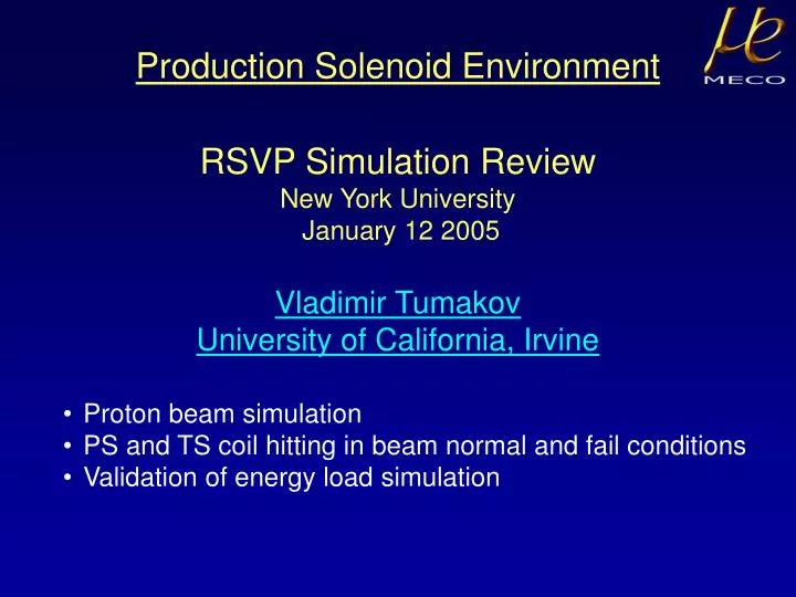
Production Solenoid Environment. RSVP Simulation Review New York University January 12 2005. Vladimir Tumakov University of California, Irvine. Proton beam simulation PS and TS coil hitting in beam normal and fail conditions Validation of energy load simulation. The MECO Apparatus.

E N D
Production Solenoid Environment RSVP Simulation Review New York University January 12 2005 Vladimir Tumakov University of California, Irvine • Proton beam simulation • PS and TS coil hitting in beam normal and fail conditions • Validation of energy load simulation
The MECO Apparatus Straw Tracker Muon Stopping Target Muon Beam Stop Superconducting Transport Solenoid (2.5 T – 2.1 T) Crystal Calorimeter Superconducting Production Solenoid (5.0 T – 2.5 T) Superconducting Detector Solenoid (2.0 T – 1.0 T) Collimators Proton Beam Heat & Radiation Shield Muon Production Target V.Tumakov Production Solenoid Environment
Water Cooled Target • Simulation and experimental tests for energy load heating and cooling • No simulation or study for target material radiation damage • Needs to be tested in the beam inlet outlet 4.5 kW energy load beam direction 0.3 mm water jacket 0.5 mm Titanium or stainless steel containment shell V.Tumakov Production Solenoid Environment
Beamline Simulation in GEANT3 18 quadrupoles and 1 dipole to make vertical pitch angle Beam direction Beam protons trajectories after the last dipole effects of solenoid field on spot size Beam profile on the target sx=1.1mm sy=0.7mm Beam direction V.Tumakov Production Solenoid Environment
Event by Event Energy Balance Distributions Envelope around the target Envelope around the shield Beam energy 5 6 7 8 9 Kinetic Energy [GeV] 5 6 7 8 9 Kinetic Energy [GeV] For estimation we used 7 MeV binding energy for each n, p, D, T, α produced in GEANT simulation Energy balance good to 3% V.Tumakov Production Solenoid Environment
Energy Removed by Particles Leaving PS Bore • PS heat shield must be water cooled (16 kW) • TS heat shield may be water cooled • Thermal management of SM bores is important Load on PS cold mass primarily from neutrons Backward energy flow requires some TS shield V.Tumakov Production Solenoid Environment
Production Solenoid Heat Shield • 50 kW beam incident on gold target (15 kW in the shield) • Superconducting magnet is protected byCu (55tons) and W (21tons) heat and radiation shield • Simulation with Geant3 Gcalor and Mars: • 60 W load on cold mass • 20 W/g instantaneous load • 20 Mrad integrated dose 2.5T 5T Cu W Superconducting coil Productiontarget Heat Shield V.Tumakov Production Solenoid Environment
TS Shield Geometry 8 2 6 2 n,p,π 6 6 4 6 4 γ or Cu 6 All dimensions are in cm V.Tumakov Production Solenoid Environment
Shield optimization Average energy deposition in TS coils with Tungsten shield is 2.2 W For some selected configurations, energy deposition is as high as 3 W Energy deposition from other sources is ~20 W V.Tumakov Production Solenoid Environment
Energy Deposition in PS and TS Coils 9 mW/g 3 mW/g Azimuthal angle 5 10 15 20 25 TS coil number 2 4 6 8 10 PS coil number 2 4 6 8 10 5 10 15 20 25 Cylindrical proton beam pipe R=4cm Azimuthal asymmetry due to targeting angle V.Tumakov Production Solenoid Environment
Transport Solenoid Shield Passive protection • 75 cm Zinc shield outside • 4 cm Copper shield inside Active protection • Ionization chambers to measure beam losses • Window frame monitors • Beam position monitors • Cryogenic magnets beam abort system 8 cm x 6 cm 18 cm x 14 cm Simulations of normal and fault beam conditions show that beam control system response time should be of order 100ms (expected about 10 ms) n,p,μ 4 cm Cu V.Tumakov Production Solenoid Environment
TS Outer Shield • Move beam up 3 cm in X projection • Muon yield does not decrease • PS coil radiation load in normal condition does not increase Quadrupole Bore Rx Ellipse radius [cm] Rx V.Tumakov Production Solenoid Environment
1000 100 10 1 1000 100 10 1 MQ12, MQ13 fields are nominal Peak Energy Deposition [mW/g] Peak Energy Deposition [mW/g] Round tube Round tube ConeElliptical tube ConeRound tubeElliptical tube 0 5 10 15 Deflection Angle [mrad] 0 5 10 15 20 Deflection Angle [mrad] Beam Pipe Optimization • Look at energy load on TS under fault conditions – quadrupole failure, last dipole failure • Compare elliptical tube profile with conical and cylindrical tube profiles Elliptical profile has best performance with combination of quadrupole and dipole failures MQ12 field is nominal MQ13 field is zero V.Tumakov Production Solenoid Environment
30 20 10 Peak Power Deposited[mW/g] -15 -10 -5 0 5 10 15 Deflection in last dipole [mrad] TS Energy Load vs Beam Deflection in X-Y Calculate temperature rise in TS coil with 30 mW/g fault load: Temperature margin is 1.5 K => no problem with quench evenwith 500 ms beam abort V.Tumakov Production Solenoid Environment
neutrons / proton 0 2 4 6 8 10 12 14 Proton Energy [GeV] Validation of MC Neutron Production and Transport Total neutron flux from 20cm Pb target MARS and GCALOR agree with data for total neutron flux Some evidence simulations may underestimate high energy neutrons – important for PS heating >100MeV >1MeV >20MeV Neutrons flux from 3.7 GeV protons vs. cos(q) V.Tumakov Production Solenoid Environment
Conclusions • GEANT3, GEANT4, and MARS simulations all show that energy deposition in PS and TS coils should not be a problem • Limited data has been found to validate the neutron flux (particularly at high energy), which is important for PS coils • Experimental data from shielding experiments would be useful • We should allow some contingency in design of PS magnet’s ability to handle nuclear heat load V.Tumakov Production Solenoid Environment