Download
1 / 34
340 likes | 343 Views
Stefan Ritt. Paul Scherrer Institute. Limiting factors in Switched Capacitor Arrays Sampling speed, Timing accuracy, Readout speed. Follow-up: Optimal Sampling Speed. Theory (Nyquist): 1 GHz signal: 350 ps rise-time, 2 GSPS. 350 ps. Threshold. 500 ps.

E N D
Stefan Ritt Paul Scherrer Institute Limiting factors in Switched Capacitor ArraysSampling speed, Timing accuracy, Readout speed Timing Workshop, Chicago
Follow-up: Optimal Sampling Speed Theory (Nyquist): 1 GHz signal: 350 ps rise-time, 2 GSPS 350 ps Threshold 500 ps Reality: Noise! (e.g. quantization noise of ADC) and tail of input power Timing Workshop, Chicago
Measured Resol. Mod724, 14 bit, 100 MS/s 5*T 50 mV StdDev (ns) 100 mV 200 mV 500 mV C. Tintori Timing Workshop, Chicago
Switched Capacitor Array 0.2-2 ns Inverter “Domino” ring chain IN Waveform stored Out FADC 33 MHz Clock Shift Register “Time stretcher” GHz MHz DPP Workshop PSI
Limits on sampling speed vs. technology Timing Workshop, Chicago
Inverter chain RC-delay with TG Starved inverters • Layout more compact • Used in DRS4 chip • TG in signal path • Parasitics of TG counts • Used in most designs • “Starving” trans. outside signal path • Parasitics do not count Timing Workshop, Chicago
Achievable sampling speeds DRS4 • Starved inverters better than TG • Speed does not linearly scale with technology(parasitics limited) • High speed (low Vt) option helps Timing Workshop, Chicago
Today highest sampling speed 130 IBM, J.-F. Genat, Clermont-Ferrand, Jan. 2011 Timing Workshop, Chicago
Interleaved sampling • Fine tuning delays STURM chip (Gary): O(100 GSPS) • For fixed interleaving, this can also be achieved by chip layout • Alternative: Comparators with different thresholds Timing Workshop, Chicago
Limits on analog bandwidth Parasitics, bond wires, Ron of sampling cell Timing Workshop, Chicago
Detector (covered in next talks) Connector (LEMO connector has a BW of ∼500 MHz) Cable (RG58: 5 m has a -3db BW of 1 GHz) PCB Preamplifier Chip package On-chip bus Analog cell switch Storage capacitor Signal Chain PCB Chip Det. Cpar Timing Workshop, Chicago
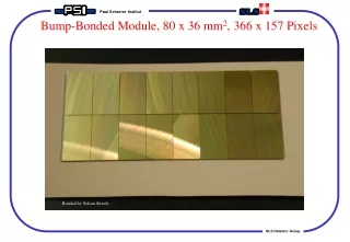
Influence on chip package Bond wire has ~2-3 nH and thus limits the BW to 2-3 GHz Input inductance can be reduced by using bump bonding or stud bonding Stud Bump 200 mm Wire 75 mm Timing Workshop, Chicago
Effect of “write bus” Length: 3500 u Widths: 4x8u, 4x14u (beginning/end of bus) DRS3: 300 MHz with 2mm width Timing Workshop, Chicago
Influence on parasitics • Minimal write switch has ~10 fF parasitic capacitance • Write bus has resistance of ~0.05 Ohm/square (0.013 Ohm square for 20k top metal option)→ 15 Ohm after 3 mm bus + bond wire (1.5 Ohm)→ 10 pF after 3 mm DRS3: 300 MHz with 2u width DRS4 Timing Workshop, Chicago
Influence of write switch • Write switch has a finite “on” resistance • Storage cap needs to be >10 fF forreasonable kTC noise • Leakage current requires even bigger C • Simulation • Cstore = 50 fF • UMC 0.25 um technology • Vdd = 2.5V • Minimal l • W = 0.25 um * N • Note: N>1 adds parasitic to write bus! -3db Bandwidth [GHz] wopt. ~ 6 um Timing Workshop, Chicago
Effect on sampling capacitor • Smaller Cstore leads to higher bandwidth • But: kTC noise → 20 fF for 11 bits • Practical limit: ∼ 5 fF • Important: Leakage current! • Worse with smaller technologies • Non-Gaussian distribution on chip • Worse for low Ron switch • Temperature dependent G. Varner Timing Workshop, Chicago
Leakage current • Leakage current: Must be small to get DV<<1mV during readout • Distribution has long tail • Either make C large orkeep storage time short G. Varner, 2010, Krakov Timing Workshop, Chicago
Comparison between technologies UMC 0.25 7 kW 6 mm opt. 16 GHz UMC 0.11 5 kW 180 mm opt. 21 GHz UMC 0.11 low Vt 4 kW 120 mm opt. 37 GHz dI/dU Ron [kW] VDS [V] BW [GHz] N/1000 Timing Workshop, Chicago
Bandwidth DRS4 (1024 sampling cells) Bandwidth is determined by bond wire and internalbus resistance/capacitance: 850 MHz (QFP), 950 MHz (QFN), ??? (flip-chip) finalbus width QFP package 850 MHz (-3dB) Simulation Measurement Timing Workshop, Chicago
Bandwidth STURM2 (32 sampling cells) G. Varner, Dec. 2009 Timing Workshop, Chicago
Optimal Chip Layout Bond Pad write+ … 32 sampling cells write- Bond Pad Timing Workshop, Chicago
Limits on timing resolution Matching – PLL phase jitter – Aperture Timing Workshop, Chicago
Typical SCA PLL • “Matching” (inverter-to-inverter variation by statistical limits in doping) is fixed over time and can be corrected • PLL phase jitter is typical 25 ps can can be corrected for with separate timing channel (DRS4: 8+1 channels) • Residual cell jitter caused by Vdd noise, short delay line is better Inverter Chain sampling speed control PLL F1 T Q Phase Comparator up loop filter down External Reference Clock F2 Timing Workshop, Chicago
Residual aperture jitter • Vdd (GND) noise causes jitter • Effect worse if rise time is slow (starving) • Typical values: • 100 ps rise time for 1.2 V signal • 5 mV noise • 32 cells • Jitter: 5 mV/1.2 V * 100 ps * 32 = 13 ps • Noise can originate off-chip (e.g. running ADC) • Solution: Differential inverters, LDO on chip • Disadvantage: More power Noise Timing Timing Workshop, Chicago
Limits on readout speed Analog-Digital readout, multi-buffer Timing Workshop, Chicago
Readout time N input channels M output channels treadout = N/M * nsamples * tsample Analog: tsample = 20 – 100 ns (external ADC 10-50 MHz) Digital: tsample = 5 – 10 ns * nbits / nlines 1024 samples, 10 bits, N=8, M=1 → treadout = 400 ms 32 samples, 10 bits, N=8, M=8 → treadout = 1.6 ms Timing Workshop, Chicago
ROI readout mode in DRS4 delayed trigger stop normal trigger stop after latency stop Trigger Delay 33 MHz readout shift register Patent pending! FEE2010, Bergamo
Multi buffering “Multi-buffering” can reduce dead time for Poisson-distributed events Event occurring during readout of first event is stored in second buffer Event is stored in first buffer R = 1 kHz, T=400 ms R: event rate [Hz] T: readout time [s] LT: “live time” N: Number of buffers Cumulative distribution function for Poisson-distributed events: Timing Workshop, Chicago
Storage Depth • Has to accommodate trigger delay • High energy physics experiments require 100’s of buffered events • CMS: Possible hit every bunch crossing at 25 ns, 155 bunch crossings before L1 trigger • ILC: ∼3000 bunch trains ∼ 5 Hz • TOF-PET: > MHz event rate CTA → Deep storage depth → Many storage segments → High event rate ILC Timing Workshop, Chicago
The vision for the future Low power Low number of input cells The Perfect Chip Highchanneldensity Deep Sampling Depth Highevent rate Manyanalogbuffers Timing Workshop, Chicago Highevent rate
Cascaded Switched Capacitor Arrays input shift register • 32 fast sampling cells at 10 GSPS • 100 ps sample time, 3.1 ns hold time • Hold time long enough to transfer voltage to secondary sampling stage with moderately fast buffer (300 MHz) • Shift register gets clocked by inverter chain from fast sampling stage . . . . . . . . . . . . . . . . . . . . . . . . . . . . . . . . . fast sampling stage secondary sampling stage DPP Workshop PSI
Typical Waveform Only short segments of waveform are of interest DPP Workshop PSI
Dead-time free acquisition Self-trigger writing of 128 short 32-bin segments (4096 bins total) Simultaneous writing and reading ofsegments Quasi dead time-free Data driven readout Ext. ADC runs continuously ASIC tells FPGA when there is new data Possibility to skip segments → analogbuffer for HEP experiments Coarse timing from300 MHz counter Fine timing by waveformdigitizing and analysis in FPGA 20 * 20 ns = 0.4 ms readout time 2 MHz sustained event rate (ToF-PET) Attractive replacement for CFD+TDC DRS5planned for 2013 DPP Workshop PSI
Conclusions • SCAs will more and more replace Q-ADC and CFG+TDCs • New designs are in the pipeline for >3 GHz analog BW, multi-buffering and fast readout • Current limitations areare well known and will bepushed further in nextgeneration of chips Timing Workshop, Chicago