Download
1 / 29
290 likes | 294 Views
Stefan Ritt. Paul Scherrer Institute. Plans for the DRS5 Switched Capacitor Array. Agenda. DRS4 chip has been developed at PSI and has been shown at this Workshop in 2009/2010 No new chip developments since 2008, but WaveDREAM board developed at PSI CAEN VME board

E N D
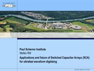
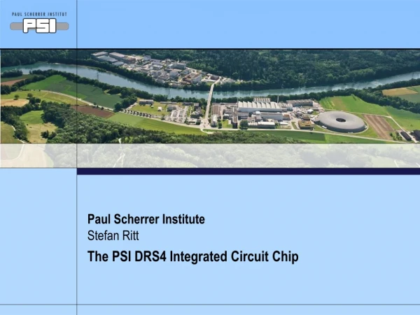
Stefan Ritt Paul Scherrer Institute Plans for the DRS5 Switched Capacitor Array Clermont Ferrand,
Agenda DRS4 chip has been developed at PSI and has been shown at this Workshop in 2009/2010 No new chip developments since 2008, but WaveDREAM board developed at PSI CAEN VME board ToF-PET Application under investigation New ideas for DRS5 to be designed in 2011 Increased bandwidth Zero dead time DRS4 Chip Evaluation Board Clermont Ferrand,
DRS4 Chip Clermont Ferrand,
DRS4 Fabricated in 0.25 mm 1P5M MMC process(UMC), 5 x 5 mm2, radiation hard 8+1 ch. each 1024 bins,4 ch. 2048, …, 1 ch. 8192 Passive differential inputs/outputs Sampling speed 700 MHz … 5 GHz On-chip PLL stabilization Readout speed 30 MHz, multiplexedor in parallel Clermont Ferrand,
Bandwidth Evaluation board Bandwidth is determined by bond wire and internalbus resistance/capacitance: 850 MHz (QFP), 950 MHz (QFN), ??? (flip-chip) QFP package finalbus width THS4508 850 MHz (-3dB) 800 MHz (-3dB) Measurement Clermont Ferrand,
ROI readout mode delayed trigger stop normal trigger stop after latency stop Trigger Delay 33 MHz e.g. 100 samples @ 33 MHz 3 us dead time 300,000 events / sec. readout shift register Patent pending! Clermont Ferrand,
Daisy-chaining of channels Domino Wave Domino Wave clock clock enable input enable input 1 Channel 0 0 Channel 0 enable input enable input 0 Channel 1 1 Channel 1 Channel 2 0 Channel 2 1 Channel 3 Channel 3 1 0 Channel 4 Channel 4 0 1 Channel 5 Channel 5 1 0 Channel 6 Channel 6 0 1 Channel 7 Channel 7 1 0 DRS4 can be partitioned in: 8x1024, 4x2048, 2x4096, 1x8192 cellsChip daisy-chaining possible to reach virtually unlimited sampling depth Clermont Ferrand,
readout Channel 0 1 Channel 0 1 0 1 Channel 1 Channel 1 Channel 2 Simultaneous Write/Read FPGA 0 Channel 0 0 Channel 1 8-foldanalog multi-eventbuffer Channel 2 0 Channel 3 0 Channel 4 0 Channel 5 0 Channel 6 0 Channel 7 0 Expected crosstalk ~few mV Clermont Ferrand,
DRS4 around the world Shipped (-Jan 2011): 2200 Chips 120 Evaluation Boards Clermont Ferrand,
MEG Status • MEG experiment @ PSI searches for meg decay • After ~10 years of chip design, DAQ setup, firmware programming, MEG runs with 3000 channels as designed • 40 ps timing resolutions between all channels, running at 1.6 GS/s • “Double buffer” readout mode increases life time to 99.7 % at 10 Hz event rate (3 MB/event) • Took 400 TB in 2010 Clermont Ferrand,
Trigger and DAQ on same board SCA can only sample a limited (1024-bin window) many application require a wider window, trigger capability would require continuous digitization Using a multiplexer in DRS4, input signals can simultaneously digitized at 120 MHz and sampled in the DRS FPGA can make local trigger(or global one) and stop DRSupon a trigger DRS readout (5 GSPS)though same 8-channel FADCs DRS4 MUX global trigger bus trigger FPGA DRS FADC12 bit 65 MHz analog front end LVDS SRAM Clermont Ferrand,
“Slow” waveform and “Fast” window TriggeredDRS Waveform 1 GSPS (1 ns bins) up to 5 GSPS Window only limited by RAM Continuous Waveform 120 MSPS (8 ns bins) Clermont Ferrand,
WaveDREAM Board Empty VME slot costs ~1kE USB is limited in speed (2.0) and scaling WaveDREAM board developed at PSI with GBit Ethernet New board planned VGA at input (10 mV – 10 V inputs) 16 Channels on Eurocard, MMCX connectors Standalone or cascadable Serial bus for data, trigger & synchronization Plug & Play Firmware: TDC, CFD, ADC, Scaler, MCA, … WaveDREAM (H. Friederich, PSI & ETH) New Board 16 chn + serial bus Eth DRS4 ADC Serial links and trigger VGA FPGA GBit Ethernet Pre- amp DRS4 ADC RAM Pre- amp Clermont Ferrand,
Digital Oscilloscope Front-end Clermont Ferrand,
Plug & Play Firmware Pre-designed modules for CFD, TDC, peak sensing ADC, … Modules can be configured by user and downloaded over Ethernet TDC FIFO CFD Chip Readout SCALER Interface FIFO FIFO ADC FIFO Data bus Parameter bus Clermont Ferrand,
CAEN V1742 Board 32+2 Channels 12 bit 5 GS/s Digitizer VME64X + optical link New board design by CAEN inline with their ADC boards Firmware support by CAEN “Early adopter phase” started2010, official board announcement March 2011 Desktop version planned Clermont Ferrand,
Digital Pulse Processing (DPP) C. Tintori (CAEN) V. Jordanov et al., NIM A353, 261 (1994) Clermont Ferrand,
g-n Pulse-shape Discrimination C. Tintori (CAEN) Clermont Ferrand,
DPP Workshop @ PSI Clermont Ferrand,
Time-of-Flight PET • Conventional electronics:CFD – TDC: 500 ps RMS • TOF needs: • 100-200 ps • >1 MHz rate C. Levin, Stanford University Clermont Ferrand,
ToF-PET Project • Started fall 2010 after NSS/MIC in Knoxville (Siemens PET R&D home) • New project started to replace current PET electronics with DRS4 (5) • PCB ready summer 2011, firmware by Univ. Tübingen • Simulations show that SCA technique can achieve 100 ps easily FPGA “Ping-Pong Scheme” 1 Channel 0 Channel 0 ROI 0 Channel 1 Channel 1 Channel 2 0 20 samples (10 ns @ 2 GS/s) * 30 ns / sample = 600 ns + 40 ns overhead = 640 ns 1 MHz rate Channel 3 0 Channel 4 0 Channel 5 0 Channel 6 0 Channel 7 0 Clermont Ferrand,
DRS5 Chip Clermont Ferrand,
Plans for DRS5 Increase analog bandwidth ~5 GHz Smaller input capacitance Increase sampling speed ~10 GS/s Switch to 180 nm technology Deeper sampling depth 8 x 4096 / chip Minimize readout time (“dead time free”) for muSR & ToF-PET (minor) reduction in analogreadout speed (30 ns 20 ns) Implement FIFO technology J. Milnes, J. Howoth, Photek mSR ~MHz event rate CTA Clermont Ferrand,
Why 180nm ? • 250 nm process dies out: 1 MPW run / year (UMC) • Pro smaller feature size: • Faster sampling speed • Faster readout (?) • More sampling cells / area (but: routing/capacitor limitation!) • Con: • Smaller VDD makes analog design difficult, with 1.2V it is almost impossible to obtain a 1V linear range • Price: 130 nm 3 x more expensive Compromise: 180 nm Clermont Ferrand,
Next Generation SCA Low parasitic input capacitance High bandwidth Large area low resistance bus, lowresistance analog switches high bandwidth Short sampling depth Deep sampling depth • Digitize long waveforms • Accommodate long trigger delay • Faster sampling speed for a given trigger latency How to combine best of both worlds? Clermont Ferrand,
Cascaded Switched Capacitor Arrays input shift register • 32 fast sampling cells (10 GSPS/180nm CMOS) • 100 ps sample time, 3.1 ns hold time • Hold time long enough to transfer voltage to secondary sampling stage with moderately fast buffer (300 MHz) • Shift register gets clocked by inverter chain from fast sampling stage . . . . . . . . . . . . . . . . . . . . . . . . . . . . . . . . . fast sampling stage secondary sampling stage Clermont Ferrand,
Typical Waveform Only short segments of waveform need high speed readout Clermont Ferrand,
Dead-time free acquisition Self-trigger writing of short 32-bin segments Simultaneous reading ofsegments Quasi dead time-free Data driven readout Ext. ADC runs continuously ASIC tells FPGA when there is new data Coarse timing from300 MHz counter Fine timing by waveformdigitizing and analysis in FPGA 20 * 20 ns = 0.4 ms readout time 2 MHz sustained event rate Attractive replacement for CFD+TDC Clermont Ferrand,
Conclusions DRS4 chip successfully used in many areas, true potential of SCA technology is just now discovered Planned DRS5 chip will increase BW and decrease readout dead time SCA technology should be able to replace most traditional electronics in particle detection Clermont Ferrand,