Download
1 / 16
200 likes | 1.85k Views
MALDI-TOF Mass 의 원리 및 응용. ( M atrix A ssisted L aser D esorption I onization – T ime O f F light Mass Spectrometry). MALDI 시료 플레이트에 준비. L aser. Sample plate. 시료 (A) 가 과량의 매트릭스 (M) 과 혼합되어 MALDI plate 에 건조됨 . 레이저 섬광이 매트릭스 분자들을 이온화함 . 시료분자들이 매트릭스로부터 proton transfer 에 의해 이온화됨 :

E N D
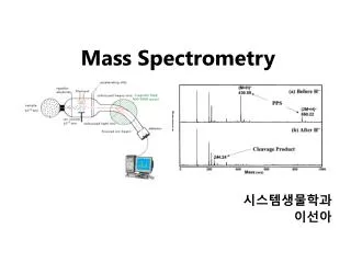
MALDI-TOF Mass의 원리 및 응용 (Matrix AssistedLaserDesorption Ionization –Time Of Flight Mass Spectrometry)
MALDI 시료 플레이트에 준비 Laser Sample plate • 시료 (A) 가 과량의 매트릭스(M)과 혼합되어 MALDI plate에 건조됨. • 레이저 섬광이 매트릭스 분자들을 이온화함. • 시료분자들이 매트릭스로부터 proton transfer 에 의해 이온화됨: • MH+ + A M + AH+. hn AH+ Ground Grid Variable Grid +20 kV • 매트릭스 는 유기산 (organic acid : M) 종류를 사용 • 여기에서는 시료가 protonation 되는 것을 설명하고 있으나, 물질에 따라 deprotonation 이 쉽게 되어 이온화 되는 경우도 있음. • 측정되는 질량값은 시료분자 (A)의 분자량+1 이거나, 분자량-1 임
Flight Tube (0.5 – 4m) Ion Source (4 – 25 KV) Detector 가벼운 이온들은 무거운 이온들보다 먼저 검출기에 도착한다. TOF에서 분자 이온들의 분리
Flight Tube Detector 4-25 kV Ion Source Reflector (Ion Mirror) Reflector TOF내 분자이온의 비행 Reflector 또는 ion mirror 는 이온발생 부위에서 동일한 질량의 이온들이 초기 에너지 분포(initial energy spread)를 갖는 것을 보정하여 분리능을 증가 시킨다. • 주어진 진공상태의 비행관 (tube) 내에서 이온이 비행할 수 있는 거리를 길게 해주어 분리능(resolution)을 향상 되는 디자인 • Peptide등의 정확한 질량 분석이 필요한 Proteomics 응용에 적합함 • Reflector (ion mirror)를 비행관의 끝에 설치하여 이온 비행 방향을 바꾸어 주고 또 하나 의 검출기(detector) 를 반대편에 설치함. • 이 디자인의 장비로는 응용에 따라 Linear 또는 Reflector 모드로 사용함
DLS & SLS 의 원리 Center for Supramolecular Nano-Assembly
DLS (Dynamic Light Scattering) < 산란광의 세기 변화 > 분자의 운동은 분자간의 상대적인 위치 변화 를 일으키게 하고 이에 따른 위상변화의 결과로 빛의 간섭현상이 시간에 따라 변화 하게 되므로 산란광의 세기가 시간에 따라 변화 즉, 산란광 세기의 시간에 따른 변화를 추적 - 분자의 운동 - 분자들의 확산 계수 - 분자의 크기를 알 수 있음 Light intensity at 0 time Photon detections < 상관 관계 함수 > I · I G() I 2 G() = I(t)I(t + ) time
DLS의 구성 DLS (Dynamic Light Scattering) 동적 광산란 실험에서는 일정한 시간 간격 (t ) 사이에 PMT( photo-multiplier tube )에 도달하는 광량자의 수를 세어서 그들 사이의 time auto-correlation function을 계산하게 된다.G() = n (t, t ) n (t+, t )
DLS (Dynamic Light Scattering) 확산계수 측정 * g(t) = 1 + Aexp(-2 Γt), Γ = 1/τ) ; 이완시간의 역수를 지수감소율 (exponential decay rate, Γ)로 정의 Semilog plot * 각도에 따른 Γ vs. q2 plot 확산계수와 지수감소율 사이의 관계 * Γ = Dq2 Stokes-Einstein 식 이용 (D = kT/f, f = 6πηRh) * Rh를 결정
100 nm SEM H2O THF TEM J. Am. Chem. Soc. 2004,126, 6294.
A 100nm 100 nm A B 18nm 50 nm B C 3nm C 10 nm 1 10 100 1000 10000 Radius (nm) TEM DLS J. Am. Chem. Soc. 2004,in press
1.203 mg/mL 1.013 0.845 0.50 c = 0 q = 0 Zimm Plot of a PS Standard
Static Light Scattering in water/THF Aggregation number 2.18 x 10⁷ g/mol (micelle)/ 2,100 (rod-coil) = 10,400 Area per molecule 4(48.8 nm)2 / 10,400 = 2.88 nm2 / molecule Rg/ Rh = 48.8/44.2 = 1.10 Rg/Rh Uniform sphere: 0.774 Polymer coil: 1.50 Spherical Shell: 1.0
q2/cm-2 Calculation of Rg ln(I(q))