Download
1 / 56
690 likes | 1.07k Views
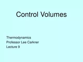
Chapter 5 Mass and Energy Analysis of Control Volumes Study Guide in PowerPoint to accompany Thermodynamics: An Engineering Approach , 5th edition by Yunus A. Çengel and Michael A. Boles. Conservation of Energy for Control volumes

E N D
Chapter 5Mass and Energy Analysis of Control VolumesStudy Guide in PowerPointto accompanyThermodynamics: An Engineering Approach, 5th editionby Yunus A. Çengel and Michael A. Boles
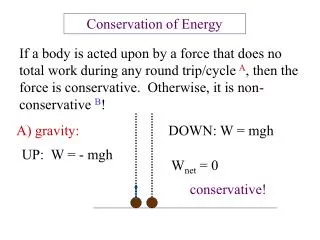
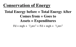
Conservation of Energy for Control volumes The conservation of mass and the conservation of energy principles for open systems or control volumes apply to systems having mass crossing the system boundary or control surface. In addition to the heat transfer and work crossing the system boundaries, mass carries energy with it as it crosses the system boundaries. Thus, the mass and energy content of the open system may change when mass enters or leaves the control volume. Thermodynamic processes involving control volumes can be considered in two groups: steady-flow processes and unsteady-flow processes. During a steady-flow process, the fluid flows through the control volume steadily, experiencing no change with time at a fixed position.
Let’s review the concepts of mass flow rate and energy transport by mass. One should study the development of the general conservation of mass presented in the text. Here we present an overview of the concepts important to successful problem solving techniques. Mass Flow Rate Mass flow through a cross-sectional area per unit time is called the mass flow rate . Note the dot over the mass symbol indicates a time rate of change. It is expressed as where is the velocity normal to the cross-sectional flow area.
If the fluid density and velocity are constant over the flow cross-sectional area, the mass flow rate is where is the density, kg/m3 ( = 1/v), A is the cross-sectional area, m2; and is the average fluid velocity normal to the area, m/s. Example 5-1 Refrigerant-134a at 200 kPa, 40% quality, flows through a 1.1-cm inside diameter, d, tube with a velocity of 50 m/s. Find the mass flow rate of the refrigerant-134a. At P = 200 kPa, x = 0.4 we determine the specific volume from
The fluid volume flowing through a cross-section per unit time is called the volume flow rate . The volume flow rate is given by integrating the product of the velocity normal to the flow area and the differential flow area over the flow area. If the velocity over the flow area is a constant, the volume flow rate is given by (note we are dropping the “ave” subscript on the velocity) The mass and volume flow rate are related by Example 5-2 Air at 100 kPa, 50oC, flows through a pipe with a volume flow rate of 40 m3/min. Find the mass flow rate through the pipe, in kg/s. Assume air to be an ideal gas, so
Conservation of Mass for General Control Volume The conservation of mass principle for the open system or control volume is expressed as or Steady-State, Steady-Flow Processes Most energy conversion devices operate steadily over long periods of time. The rates of heat transfer and work crossing the control surface are constant with time. The states of the mass streams crossing the control surface or boundary are constant with time. Under these conditions the mass and energy content of the control volume are constant with time.
Steady-state, Steady-Flow Conservation of Mass: Since the mass of the control volume is constant with time during the steady-state, steady-flow process, the conservation of mass principle becomes or Special Case: Steady Flow of an Incompressible Fluid The mass flow rate is related to volume flow rate and fluid density by For one entrance, one exit steady flow control volume, the mass flow rates are related by
1 2 Incompressible Liquid 2D D Word of caution: This result applies only to incompressible fluids. Most thermodynamic systems deal with processes involving compressible fluids such as ideal gases, steam, and the refrigerants for which the above relation will not apply. Example 5-3 Geometry Effects on Fluid Flow An incompressible liquid flows through the pipe shown in the figure. The velocity at location 2 is
Solution: Answer: D
Flow work and the energy of a flowing fluid Energy flows into and from the control volume with the mass. The energy required to push the mass into or out of the control volume is known as the flow work or flow energy. The fluid up steam of the control surface acts as a piston to push a unit of mass into or out of the control volume. Consider the unit of mass entering the control volume shown below. As the fluid upstream pushes mass across the control surface, work done on that unit of mass is
The term Pv is called the flow work done on the unit of mass as it crosses the control surface. The total energy of flowing fluid The total energy carried by a unit of mass as it crosses the control surface is the sum of the internal energy, flow work, potential energy, and kinetic energy. Here we have used the definition of enthalpy, h = u + Pv. Energy transport by mass Amount of energy transport across a control surface:
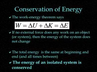
Rate of energy transport across a control surface: Conservation of Energy for General Control Volume The conservation of energy principle for the control volume or open system has the same word definition as the first law for the closed system. Expressing the energy transfers on a rate basis, the control volume first law is or Considering that energy flows into and from the control volume with the mass, energy enters because net heat is transferred to the control volume, and energy leaves because the control volume does net work on its surroundings, the open system, or control volume, the first law becomes
where is the energy per unit mass flowing into or from the control volume. The energy per unit mass, , flowing across the control surface that defines the control volume is composed of four terms: the internal energy, the kinetic energy, the potential energy, and the flow work. The total energy carried by a unit of mass as it crosses the control surface is Where the time rate change of the energy of the control volume has been written as
Steady-State, Steady-Flow Processes Most energy conversion devices operate steadily over long periods of time. The rates of heat transfer and work crossing the control surface are constant with time. The states of the mass streams crossing the control surface or boundary are constant with time. Under these conditions the mass and energy content of the control volume are constant with time. Steady-state, Steady-Flow Conservation of Mass: Steady-state, steady-flow conservation of energy Since the energy of the control volume is constant with time during the steady-state, steady-flow process, the conservation of energy principle becomes
0 or or Considering that energy flows into and from the control volume with the mass, energy enters because heat is transferred to the control volume, and energy leaves because the control volume does work on its surroundings, the steady-state, steady-flow first law becomes
Often this result is written as where Steady-state, steady-flow for one entrance and one exit A number of thermodynamic devices such as pumps, fans, compressors, turbines, nozzles, diffusers, and heaters operate with one entrance and one exit. The steady-state, steady-flow conservation of mass and first law of thermodynamics for these systems reduce to
where the entrance to the control volume is state 1 and the exit is state 2 and is the mass flow rate through the device. When can we neglect the kinetic and potential energy terms in the first law? Consider the kinetic and potential energies per unit mass.
When compared to the enthalpy of steam (h 2000 to 3000 kJ/kg) and the enthalpy of air (h 200 to 6000 kJ/kg), the kinetic and potential energies are often neglected. When the kinetic and potential energies can be neglected, the conservation of energy equation becomes We often write this last result per unit mass flow as where and . Some Steady-Flow Engineering Devices Below are some engineering devices that operate essentially as steady-state, steady-flow control volumes.
Nozzles and Diffusers For flow through nozzles, the heat transfer, work, and potential energy are normally neglected, and nozzles have one entrance and one exit. The conservation of energy becomes
Solving for Example 5-4 Steam at 0.4 MPa, 300oC, enters an adiabatic nozzle with a low velocity and leaves at 0.2 MPa with a quality of 90%. Find the exit velocity, in m/s. Control Volume: The nozzle Property Relation: Steam tables Process: Assume adiabatic, steady-flow Conservation Principles: Conservation of mass: For one entrance, one exit, the conservation of mass becomes
Conservation of energy: According to the sketched control volume, mass crosses the control surface, but no work or heat transfer crosses the control surface. Neglecting the potential energies, we have Neglecting the inlet kinetic energy, the exit velocity is Now, we need to find the enthalpies from the steam tables. At 0.2 MPa hf = 504.7 kJ/kg and hfg = 2201.6 kJ/kg.
Turbines If we neglect the changes in kinetic and potential energies as fluid flows through an adiabatic turbine having one entrance and one exit, the conservation of mass and the steady-state, steady-flow first law becomes
Example 5-5 High pressure air at 1300 K flows into an aircraft gas turbine and undergoes a steady-state, steady-flow, adiabatic process to the turbine exit at 660 K. Calculate the work done per unit mass of air flowing through the turbine when (a) Temperature-dependent data are used. (b) Cp,ave at the average temperature is used. (c) Cp at 300 K is used.
Control Volume: The turbine. Property Relation: Assume air is an ideal gas and use ideal gas relations. Process: Steady-state, steady-flow, adiabatic process Conservation Principles: Conservation of mass: Conservation of energy: According to the sketched control volume, mass and work cross the control surface. Neglecting kinetic and potential energies and noting the process is adiabatic, we have
The work done by the air per unit mass flow is Notice that the work done by a fluid flowing through a turbine is equal to the enthalpy decrease of the fluid. (a) Using the air tables, Table A-17 at T1 = 1300 K, h1 = 1395.97 kJ/kg at T2 = 660 K, h2 = 670.47 kJ/kg
(b) Using Table A-2(c) at Tave = 980 K, Cp, ave= 1.138 kJ/kgK (c) Using Table A-2(a) at T = 300 K, Cp = 1.005 kJ/kg K Compressors and fans
Compressors and fans are essentially the same devices. However, compressors operate over larger pressure ratios than fans. If we neglect the changes in kinetic and potential energies as fluid flows through an adiabatic compressor having one entrance and one exit, the steady-state, steady-flow first law or the conservation of energy equation becomes Example 5-6 Nitrogen gas is compressed in a steady-state, steady-flow, adiabatic process from 0.1 MPa, 25oC. During the compression process the temperature becomes 125oC. If the mass flow rate is 0.2 kg/s, determine the work done on the nitrogen, in kW.
Control Volume: The compressor (see the compressor sketched above) Property Relation: Assume nitrogen is an ideal gas and use ideal gas relations Process: Adiabatic, steady-flow Conservation Principles: Conservation of mass: Conservation of energy: According to the sketched control volume, mass and work cross the control surface. Neglecting kinetic and potential energies and noting the process is adiabatic, we have for one entrance and one exit
The work done on the nitrogen is related to the enthalpy rise of the nitrogen as it flows through the compressor. The work done on the nitrogen per unit mass flow is Assuming constant specific heats at 300 K from Table A-2(a), we write the work as
Throttling devices Consider fluid flowing through a one-entrance, one-exit porous plug. The fluid experiences a pressure drop as it flows through the plug. No net work is done by the fluid. Assume the process is adiabatic and that the kinetic and potential energies are neglected; then the conservation of mass and energy equations become
This process is called a throttling process. What happens when an ideal gas is throttled? When throttling an ideal gas, the temperature does not change. We will see later in Chapter 11 that the throttling process is an important process in the refrigeration cycle. A throttling device may be used to determine the enthalpy of saturated steam. The steam is throttled from the pressure in the pipe to ambient pressure in the calorimeter. The pressure drop is sufficient to superheat the steam in the calorimeter. Thus, the temperature and pressure in the calorimeter will specify the enthalpy of the steam in the pipe.
Throttling orifice 1 2 Example 5-7 One way to determine the quality of saturated steam is to throttle the steam to a low enough pressure that it exists as a superheated vapor. Saturated steam at 0.4 MPa is throttled to 0.1 MPa, 100oC. Determine the quality of the steam at 0.4 MPa. Control Surface Control Volume: The throttle Property Relation: The steam tables Process: Steady-state, steady-flow, no work, no heat transfer, neglect kinetic and potential energies, one entrance, one exit Conservation Principles: Conservation of mass:
Conservation of energy: According to the sketched control volume, mass crosses the control surface. Neglecting kinetic and potential energies and noting the process is adiabatic with no work, we have for one entrance and one exit Therefore,
Mixing chambers The mixing of two fluids occurs frequently in engineering applications. The section where the mixing process takes place is called a mixing chamber. The ordinary shower is an example of a mixing chamber.
Steam 1 Saturated water 3 Mixing chamber Cold water 2 Control surface Example 5-8 Steam at 0.2 MPa, 300oC, enters a mixing chamber and is mixed with cold water at 20oC, 0.2 MPa, to produce 20 kg/s of saturated liquid water at 0.2 MPa. What are the required steam and cold water flow rates? Control Volume: The mixing chamber Property Relation: Steam tables Process: Assume steady-flow, adiabatic mixing, with no work Conservation Principles: Conservation of mass:
Conservation of energy: According to the sketched control volume, mass crosses the control surface. Neglecting kinetic and potential energies and noting the process is adiabatic with no work, we have for two entrances and one exit Now, we use the steam tables to find the enthalpies:
Heat exchangers Heat exchangers are normally well-insulated devices that allow energy exchange between hot and cold fluids without mixing the fluids. The pumps, fans, and blowers causing the fluids to flow across the control surface are normally located outside the control surface.
1 Air inlet 1 Water inlet Control surface 2 Water exit 2 Air exit Example 5-9 Air is heated in a heat exchanger by hot water. The water enters the heat exchanger at 45oC and experiences a 20oC drop in temperature. As the air passes through the heat exchanger, its temperature is increased by 25oC. Determine the ratio of mass flow rate of the air to mass flow rate of the water. Control Volume: The heat exchanger Property Relation: Air: ideal gas relations Water: steam tables or incompressible liquid results Process: Assume adiabatic, steady-flow
0(steady) Conservation Principles: Conservation of mass: For two entrances, two exits, the conservation of mass becomes For two fluid streams that exchange energy but do not mix, it is better to conserve the mass for the fluid streams separately. Conservation of energy: According to the sketched control volume, mass crosses the control surface, but no work or heat transfer crosses the control surface. Neglecting the kinetic and potential energies, we have for steady-flo
0(steady) We assume that the air has constant specific heats at 300 K, Table A-2(a) (we don't know the actual temperatures, just the temperature difference). Because we know the initial and final temperatures for the water, we can use either the incompressible fluid result or the steam tables for its properties. Using the incompressible fluid approach for the water, Table A-3, Cp, w= 4.18 kJ/kgK.
A second solution to this problem is obtained by determining the heat transfer rate from the hot water and noting that this is the heat transfer rate to the air. Considering each fluid separately for steady-flow, one entrance, and one exit, and neglecting the kinetic and potential energies, the first law, or conservation of energy, equations become
Steam to turbine 2 1 Steam from boiler Control surface Pipe and duct flow The flow of fluids through pipes and ducts is often a steady-state, steady-flow process. We normally neglect the kinetic and potential energies; however, depending on the flow situation, the work and heat transfer may or may not be zero. Example 5-10 In a simple steam power plant, steam leaves a boiler at 3 MPa, 600oC, and enters a turbine at 2 MPa, 500oC. Determine the in-line heat transfer from the steam per kilogram mass flowing in the pipe between the boiler and the turbine. Control Volume: Pipe section in which the heat loss occurs. Property Relation: Steam tables Process: Steady-flow Conservation Principles:
0(steady) 0(steady) Conservation of mass: For one entrance, one exit, the conservation of mass becomes Conservation of energy: According to the sketched control volume, heat transfer and mass cross the control surface, but no work crosses the control surface. Neglecting the kinetic and potential energies, we have for steady-flow We determine the heat transfer rate per unit mass of flowing steam as
We use the steam tables to determine the enthalpies at the two states as Example 5-11 Air at 100oC, 0.15 MPa, 40 m/s, flows through a converging duct with a mass flow rate of 0.2 kg/s. The air leaves the duct at 0.1 MPa, 113.6 m/s. The exit-to-inlet duct area ratio is 0.5. Find the required rate of heat transfer to the air when no work is done by the air.
Air exit 2 1 Air inlet Control surface 0(steady) Control Volume: The converging duct Property Relation: Assume air is an ideal gas and use ideal gas relations Process: Steady-flow Conservation Principles: Conservation of mass: For one entrance, one exit, the conservation of mass becomes
0(steady) Conservation of energy: According to the sketched control volume, heat transfer and mass cross the control surface, but no work crosses the control surface. Here keep the kinetic energy and still neglect the potential energies, we have for steady-state, steady-flow process In the first law equation, the following are known: P1, T1 (and h1), , , , and A2/A1. The unknowns are , and h2 (or T2). We use the first law and the conservation of mass equation to solve for the two unknowns.
Solving for T2 Assuming Cp = constant, h2 - h1 = Cp(T2 - T1)
Looks like we made the wrong assumption for the direction of the heat transfer. The heat is really leaving the flow duct. (What type of device is this anyway?) Liquid pumps The work required when pumping an incompressible liquid in an adiabatic steady-state, steady-flow process is given by The enthalpy difference can be written as
For incompressible liquids we assume that the density and specific volume are constant. The pumping process for an incompressible liquid is essentially isothermal, and the internal energy change is approximately zero (we will see this more clearly after introducing the second law). Thus, the enthalpy difference reduces to the difference in the pressure-specific volume products. Since v2 = v1 = v the work input to the pump becomes is the net work done by the control volume, and it is noted that work is input to the pump; so, . If we neglect the changes in kinetic and potential energies, the pump work becomes We use this result to calculate the work supplied to boiler feedwater pumps in steam power plants. If we apply the above energy balance to a pipe section that has no pump ( ), we obtain.