Download
1 / 61
690 likes | 773 Views
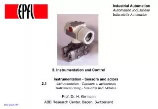
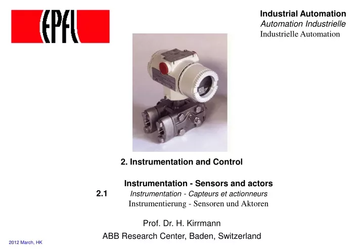
Industrial Automation Automation Industrielle Industrielle Automation. 2. Instrumentation and Control. courtesy ABB. Instrumentation - Sensors and actors 2.1 Instrumentation - Capteurs et actionneurs Instrumentierung - Sensoren und Aktoren. Prof. Dr. H. Kirrmann.

E N D
Industrial Automation Automation IndustrielleIndustrielle Automation 2. Instrumentation and Control courtesy ABB Instrumentation - Sensors and actors2.1Instrumentation - Capteurs et actionneurs Instrumentierung - Sensoren und Aktoren Prof. Dr. H. Kirrmann ABB Research Center, Baden, Switzerland 2012 March, HK
2.1.1 Market • 2.1 Instrumentation • 2.1.1 Market • 2.1.2 Binary instruments • 2.1.3 Analog Instruments • 2.1.4 Actors • 2.1.5 Transducers • 2.1.6 Instrumentation diagrams • 2.1.7 Protection classes • 2.2 Control • 2.3 Programmable Logic Controllers
The instrumentation market Emerson (Fisher-Rosemount): 27 % Invensys: 4-5% ABB: 4-5% Honeywell: 3-4% one dominant player a lot of small players…
Example Nuclear power plant Nombre de capteurs et d’actionneurs pour une tranche et selon les paliers (number of sensors and actors for each slice and according to the level) Jean CHABERT, Bernard APPELL, Guy GUESNIER, 1998
Concepts • instruments = sensors (capteurs, Messgeber) and actors (actionneurs, Stellglieder) • binary (on/off) and analog (continuous) instruments are distinguished. • industrial conditions: • temperature range commercial: (0°C to +70°C) industry (-40°C..+85°C)extended industrial(–40°C..+125°C) • mechanical resilience (shocks and vibrations) EN 60068 • protection: Electro-Magnetic (EM)-disturbances EN 55022, EN55024) • protection: water and moisture (IP67=completely sealed, IP20 = normal) • protection: NEMP (Nuclear EM Pulse) - water distribution, civil protection • mounting and replacement • robust connectors • power: DC mostly 24V= because of battery back-up, sometimes 48V=)
2.1.2 Binary Instruments • 2.1 Instrumentation • 2.1.1 Market • 2.1.2 Binary instruments • 2.1.3 Analog Instruments • 2.1.4 Actors • 2.1.5 Transducers • 2.1.6 Instrumentation diagrams • 2.1.7 Protection classes • 2.2 Control • 2.3 Programmable Logic Controllers
Binary position measurement • binary sensors (Geber,"Initiator", indicateur "tout ou rien"): • micro-switch (Endschalter, contact fin de course) +cheap, -wear, bouncing • optical sensor (Lichtschranke, barrière optique) +reliable, -dust or liquid sensitive • magnetic sensor (Näherungsschalter, détecteur de proximité) +dust-insensitive, - magnetic
Binary Signal processing • Physical attachment • Level adaptation, • Galvanical separation • EMC barrier (against sparks, radio, disturbances) • Acquisition • Convert to standard levels • Relay contacts 24V (most frequent), 48V, 110V (electrical substations) • Electronic signals 24V —>10V-60V, • Output: 0..24V@100mA • Counter inputs: Gray, BCD or binary • Processing • Filtering (e.g. 0..8 ms filter), • Plausibility (Antivalenz, Antivalence), • Bounce-free (Entprellen, Anti-rebond)
2.1.3 Analog Instruments • 2.1 Instrumentation • 2.1.1 Market • 2.1.2 Binary instruments • 2.1.3 Analog Instruments • 2.1.3.1 Position and speed • 2.1.3.2 Temperature • 2.1.3.3 Hydraulic • 2.1.4 Actors • 2.1.5 Transducers • 2.1.6 Instrumentation diagrams • 2.1.7 Protection classes • 2.2 Control • 2.3 Programmable Logic Controllers
Precision (repeatability) and accuracy (deviation) Not precise Accurate Not precise Not accurate Precise Accurate Precise Not accurate Accuracy is a consequence of systematic errors (or bad calibration) accuracy and precision may depends on time (drift)
Resolution and accuracy • Resolution expresses how many different levels can be distinguished • It is not related to accuracy
2.1.3.1 Analog mechanical position +cheap, -wear, bad resolution potentiometer capacitive balanced transformer (LVDT) (linear or sin/cos encoder) strain gauges piezo-electric +cheap, -bad resolution +reliable, robust - small displacements +reliable, very small displacements +extremely small displacements
Variable differential transformer (LVTD) The LVDT is a variable-reluctance device, where a primary centercoil establishes a magnetic flux that is coupled through a mobilearmature to a symmetrically-wound secondary coil on either sideof the primary. Two components comprise the LVDT: the mobile armature andthe outer transformer windings. The secondary coils areseries-opposed; wound in series but in opposite directions. When the moving armature is centered between the two series-opposed secondaries, equal magnetic flux couples into both secondaries; the voltage induced in one half of the secondary winding is 180 degrees out-of-phase with the voltage induced in the other half of the secondary winding. When the armature is moved out of that position, a voltage proportional to the displacement appears source: www.sensorland.com
Capacitive angle or position measurement A C = ε ≈ a d movable capacitance is evaluated by modifying the frequency of an oscillator a fixed
Small position measurement: strain gauges Dehnungsmessstreifen (DMS),jauges de contrainte Principle: the resistance of a wire with resistivity ρ increases when this wire is stretched: A ρ = resistivity l l' l2 R = r ≈ l2 = r A V l" volume = constant, r = constant measurement in bridge (if U0 = 0: R1R4 = R2R3) R1 measure R3 U temperature compensation by “dummy” gauges Uo R2 compensation R4 frequently used in buildings, bridges, dams for detecting movements.
Piezo-electrical effect Piezoelectric materials (crystals) change form when an electrical field is applied to them. Conversely, piezoelectric materials produce an electrical field when deformed. • Quartz transducers exhibit remarkable properties that justify their large scale use in research, development, production and testing. They are extremely stable, rugged and compact. • Of the large number of piezoelectric materials available today, quartz is employed preferentially in transducer designs because of the following excellent properties: • high material stress limit, around 100 MPa (~ 14 km water depth) • temperature resistance (up to 500C) • very high rigidity, high linearity and negligible hysteresis • almost constant sensitivity over a wide temperature range • ultra high insulation resistance (10+14 ohms) allowing low frequency measurements (<1 Hz) source: Kistler
Principle of optical angle encoder Optical encoders operate by means of a grating that moves between a light source and a detector. The detector registers when light passes through the transparent areas of the grating. For increased resolution, the light source is collimated and a mask is placed between the grating and the detector. The grating and the mask produce a shuttering effect, so that only when their transparent sections are in alignment is light allowed to pass to the detector. An incremental encoder generates a pulse for a given increment of shaft rotation (rotary encoder), or a pulse for a given linear distance travelled (linear encoder). Total distance travelled or shaft angular rotation is determined by counting the encoder output pulses. An absolute encoder has a number of output channels, such that every shaft position may be described by its own unique code. The higher the resolution the more output channels are required. courtesy Parker Motion & Control
Incremental angle encoder Photo: Lenord & Bauer open mounted Photo: Baumer
Absolute digital position: Gray encoder binary code: if all bits were to change at about the same time: glitches 0 1 2 3 4 5 6 7 8 9 10 11 12 13 14 15 0000 0001 0010 0011 0100 0101 0110 0111 … LSB MSB Gray code: only one bit changes at a time: no glitch 0000 0001 0011 0010 0110 0111 0101 0100 0 1 2 3 4 5 6 7 8 9 10 11 12 13 14 15 LSB courtesy Parker Motion & Control MSB Gray disk (8 bit)
Linear encoder Also with magnetic instead of optical grating
Force measurement Force / Torque / Weight / Pressure is measured by small displacements (F = k • x): - piezo-electrical transducers - strain gauges Acceleration is measured by way of force / displacement measurement (F = M • g)
N S Analog speed measurement: tachometer angular speed transducer analog: 4..20 mA digital: 010110110 Ui ~ d / dt, f ~ a simple tachometer is a rotating permanent magnet that induces a voltage into a stator winding. this voltage is converted into an analog voltage or current, later converted to a digital value, alternatively, the frequency of the signal can be measured to yield directly a digital value
Measuring distance without mechanical contact principle inductive optical ultra-sound range 0..10mm 15..1000 mm 20..2599mm resolution 0,1µm 2µm 300µm repeatability 1µm 2µm 500µm linearity 0,4..5% 0,06..1,2% 0,5% reactivity 0,35ms 0,9ms 30ms remark for electrically for small and highly linear conducting mobile parts long range materials, small dust resilient cheap CCD Example: optical rangefinder laser
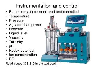
2.1.3.2 Temperature measurement the most frequently measured value in industry Protection and head assembly Extension Assemblies Thermowell www.omega.com
Temperature measurement Thermistance (RTD - resistance temperature detector): metal whose resistance depends on temperature: + cheap, robust, high temperature range ( -180ºC ..600ºC), - require current source, non-linear. Thermistor (NTC - negative temperature coefficient): semiconductor whose resistance depends on temperature: + very cheap, sensible, - low temperature, imprecise, needs current source, strongly non-linear, fragile, self-heating Thermo-element (Thermoelement, thermocouple): pair of dissimilar metals that generate a voltage proportional to the temperature difference between warm and cold junction (Seebeck effect)+ high precision, high temperature, punctual measurement- low voltage, requires cold junction compensation, high amplification, linearization Spectrometer: measures infrared radiation by photo-sensitive semiconductors + highest temperature, measures surfaces, no contact- highest price Bimetal (Bimetall, bilame): mechanical (yes/no) temperature indicator using the difference in the dilatation coefficients of two metals, very cheap, widely used (toasters...)
Thermo-element and Thermo-resistance Thermo-element (Thermocouple) 3 4 2 extension wire 1 two dissimilar electrical conductors Cu 4..20 mA Fe U ≈ (2-1) Constantan Cu Fe-Const measured temperature (hot junction) reference temperature (cold junction) also: Pt/Rh - Pt Platinum (Pt 100) Thermoresistance (semiconductor or metal) 4..20 mA i = constant one material whose resistance is temperature- dependent U ≈ 2,3- or 4-wire connection 2 or 4 wire connection (to compensate voltage drop)
2.1.3.3 Hydraulic measurements • Flow, • Mass Flow, • Level, • Pressure, • Conductivity, • pH-Sensor, • Viscosity, • Humidity, special requirements: intrinsic safety = explosive environment, sea floor = high pressure
Level measurement • pulsed laser • load cell • pulsed microwave • nuclear • ultrasonic (40-60 kHz) • low power ultrasonic F = mg detector row see Control Engineering, Aug 2003
Flow measurement • Distinguish: • volumetric flow ( m3/s) • mass flow: (kg / s) • identical when the density of the liquid is constant • main methods: • floater • turbine • pressure difference • vortex • temperature gradient • ultrasonic • electrodynamics
Flow velocity measurement: differential pressure (2 methods) piezo-electric sensor 1 2 membrane fluid of viscosity r p2 p1 v occultation (Verengung) occultation (Blende) 1 (Bernoulli effect) p2 - p1 = r v2 2 the flow velocity is proportional to the square root of the pressure difference
Flow measurement Other means: Magnetic-dynamic Coriolis Ultra-sound
2.1.4 Actors • 2.1 Instrumentation • 2.1.1 Market • 2.1.2 Binary instruments • 2.1.3 Analog Instruments • 2.1.4 Actors • 2.1.5 Transducers • 2.1.6 Instrumentation diagrams • 2.1.7 Protection classes • 2.2 Control • 2.3 Programmable Logic Controllers
Actors (Actuators) Stellantriebe, Servomoteurs About 10% of the field elements are actors (that influence the process). Actors can be binary (on/off) or analog (e.g. variable speed drive) The most common are: - electric contactors (relays) - heating elements - pneumatic and hydraulic movers (valve, pump) - electric motors (rotating and linear) Actors are controlled by the same electrical signal levels as sensors use (4..20mA, 0..10V, 0..24V, etc.) but at higher power levels, e.g. to directly move a contactor (disjoncteur).
Electric Motors Solenoids, DC motor Asynchronous Motors (Induction) Synchronous motors Step motors, reluctance motors
Drives (variateurs de vitesse, Stellantriebe) Variable speed drives control speed and acceleration and protect the motor (over-current, torque, temperature). High-power drives can feed back energy to the grid when braking (inverters). Drives is an own market (“Automation & Drives”) simple motor control cabinet for power of > 10 kW small drive control < 10 kW (Rockwell) Motors and drives are separate businesses
Linear Motors source: LinMot (/www.linmot.com)
Hydraulics and fluidics… Pumps, valves, rods,… the most widespread actor in industry(lightweight, reliable, cheap) fluidic switches I/P or E/P = electro-pneumatic transducers switchboard ("Ventilinsel") source: www.bachofen.ch
2.1.5 Transducers • 2.1 Instrumentation • 2.1.1 Market • 2.1.2 Binary instruments • 2.1.3 Analog Instruments • 2.1.4 Actors • 2.1.5 Transducers • 2.1.6 Instrumentation diagrams • 2.1.7 Protection classes • 2.2 Control • 2.3 Programmable Logic Controllers
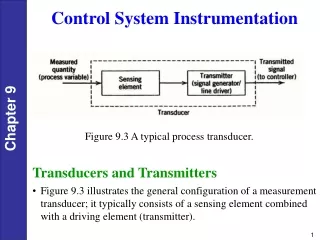
Transducer A transducer converts the information supplied by a sensor (piezo, resistance,…) into a standardized signal which can be processed digitally. Some transducers have directly a digital (field bus) output and are integrated in the sensor. Other are located at distances of several meters from the sensor.
Example of analog transducer High voltage Field house Transducer Current Transformer Protection 0..1A rms 4..20 mA R = Load Emergency panel Control Room PLC
4-20 mA loop standard voltage source Object Transducer instrument instrument instrument 1 2 3 10..24V R2 R3 R1 measurand i = f(v) 0, 4..20 mA The transducer acts as a current source which delivers a current between 4 and 20 mA, proportional to the measurand (Messgrösse, valeur mesurée). Information is conveyed by a current, the voltage drop along the cable induces no error. 0 mA signals an error (wire disconnection) The number of loads connected in series is limited by the operating voltage (10..24 V).e.g. if (R1 + R2+ R3) = 1.5 k, i = 24 / 1.5 = 16 mA, which is < 20 mA: NOT o.k.) Simple devices are powered directly by the residual current (4mA) allowing to transmit signal and power through a single pair of wires.
Analog measurements processing in the transducer Acquisition (Erfassung/Saisie) Normalized Signals: 0-10V, 2-10V, (0/4-20mA), ±20mA, Resistance thermometer (Pt100), Thermo-element Shaping (Aufbereitung/conditionnement) Filtering against 50Hz/60Hz noise and its harmonics Scaling, Linearization of sensors (Pt100, Fe-Const), correction (square root for flow). Averaging and Computation of Root Mean Square (Effektivwert, valeur efficace), Analog-Digital Conversion Plausibility Range, Limit supervision, Wire integrity Error report, diagnostic, disabling. Combined measurement Correction of pressure and temperature measurement for moist gases, correction of level in function of pressure, power and energy computation, cumulative measurements
2.1.6 Instrumentation diagrams: P&ID • 2.1 Instrumentation • 2.1.1 Market • 2.1.2 Binary instruments • 2.1.3 Analog Instruments • 2.1.4 Actors • 2.1.5 Transducers • 2.1.6 Instrumentation diagrams • 2.1.7 Protection classes • 2.2 Control • 2.3 Programmable Logic Controllers
Instrumentation Diagrams Similarly to electrical schemas, the control industry (especially the chemical and process industry) describes its plants and their instrumentation by a P&ID (pronounce P.N.I.D.) (Piping aNd Instrumentation Diagram), sometimes called P&WD (Piping and wiring diagrams) The P&ID shows the flows in a plant (in the chemical or process industry) and the corresponding sensors or actors. At the same time, the P&ID gives a name ("tag") to each sensor and actor, along with additional parameters. This tag identifies a "point" not only on the screens and controllers, but also on the objects in the field.
P&ID The P&ID mixes pneumatic / hydraulic elements, electrical elements and instruments on the same diagram It uses a set of symbols defined in the ISA S5.1 standard. Examples of pneumatic / hydraulic symbols: pipe heater 350 kW valve one-way valve (“diode”) vessel / reactor binary (or solenoid) valve (on/off) analog valve (continuous) heat exchanger pump, also
Instrumentation identification The first letter defines the measured or initiating variables such as Analysis (A), Flow (F), Temperature (T), etc. with succeeding letters defining readout, passive, or output functions such as Indicator (I), Record (R), Transmit (T), see next slides, here: flow indicator digital FIC V1528 tag name of the correspondingvariablehere: V1528 mover (here: solenoid) S function (here: valve)
ISA S5.1 General instrument or function symbols Primary location accessible to operator Field mounted Auxiliary location accessible to operator Discrete instruments Shared display, shared control Computer function Programmable logic control 1. Symbol size may vary according to the user's needs and the type of document.2. Abbreviations of the user's choice may be used when necessary to specify location.3. Inaccessible (behind the panel) devices may be depicted using the same symbol but with a dashed horizontal bar. Source: Control Engineering with data from ISA S5.1 standard