Download
1 / 1
10 likes | 177 Views
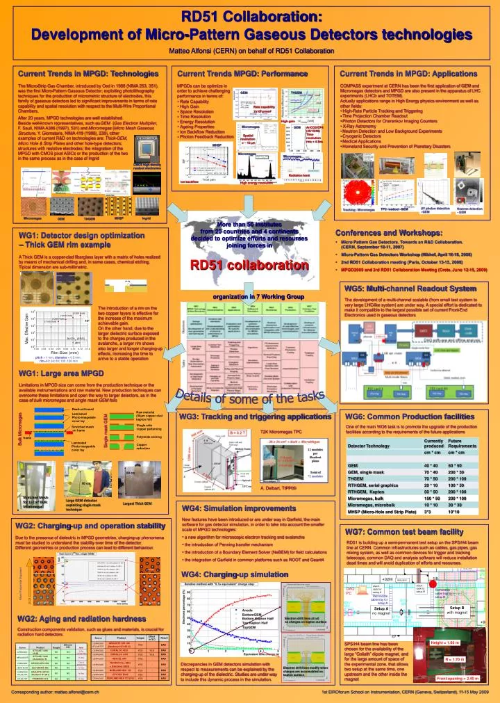
0.18 m m CMOS VLSI. 3M A3. 3M B2. Height = 1.06 m. Gas panel. electr. rack for setup B. electr. rack for setup A. DAQ PC. 10 4. Removable cable tray for setup B. Ions. TE347-6. R = 1.70 m. Removable cable tray for setup A. 40 %. 60 %. Electrons. Setup B with magnet.

E N D
0.18 mm CMOS VLSI 3M A3 3M B2 Height = 1.06 m Gas panel electr. rack for setup B electr. rack for setup A DAQPC 104 Removable cable tray for setup B Ions TE347-6 R = 1.70 m Removable cable tray for setup A 40 % 60 % Electrons Setup Bwith magnet Setup A no magnet 6 keV X-ray Std CERN1 Scienergy-65 Front opening = 2.40 m Spatial resolution s ~ 12 mm MPGDs can be optimize in order to achieve challenging performance in terms of: The Micro-Strip Gas Chamber, introduced by Oed in 1988 (NIMA 263, 351), was the first Micro-Pattern Gaseous Detector; exploiting photolithography techniques for the production of micrometric structure of electrodes, this family of gaseous detectors led to significant improvements in terms of rate capability and spatial resolution with respect to the Multi-Wire Proportional Chambers. GEM THGEM pitch = 1 mm; diameter = 0.5 mm; rim=40; 60; 80; 100; 120 mm • Rate Capability • High Gain • Space Resolution • Time Resolution • Energy Resolution • Ageing Properties • Ion Backflow Reduction • Photon Feedback Reduction Rate capability 2x10⁶ p/mm2 7 High gain After 20 years, MPGD technologies are well established. Beside well-known representatives, such as GEM (Gas Electron Multiplier, F. Sauli, NIMA A386 (1997), 531) and Micromegas (Micro Mesh Gaseous Micromegas GEM Ar/CO2/CF4 (45/15/40) Time resolution rms = 4.5ns Structure,Y. Giomataris, NIMA 419 (1998), 239), other examples of current R&D on technologies are: Thick-GEM, Micro Hole & Strip Plates and other hole-type detectors; structures with resistive electrodes; the integration of the MPGD with CMOS pixel ASICs or the production of the two in the same process as in the case of Ingrid MHSP Micromegas Micromegas CMOS high density readout electronics Radiation hard Ion backflow High energy resolution UV photon detection- GEM Neutron detection- GEM TPC readout - GEM Tracking - Micromegas Micromegas MHSP Ingrid GEM THGEM A Thick GEM is a copper-clad fiberglass layer with a matrix of holes realized by means of mechanical drilling and, in some cases, chemical etching. Tipical dimension are sub-millimetric. The introduction of a rim on the two copper layers is effective for the increase of the maximum achievable gain.On the other hand, due to the larger dielectric surface exposed to the charges produced in the avalanche, a larger rim shows also larger and longer charging-up effects, increasing the time to arrive to a stable operation WG1: Large area MPGD Limitations in MPGD size can come from the production technique or the available instrumentations and raw material. New production techniques can overcome these limitations and open the way to larger detectors, as in the case of bulk micromegas and single mask GEM foils Read-out board Raw material(50μm copper-clad kapton foil) Laminated Photo-imageable cover lay Single side copper patterning Stretched mesh on frame Bulk Micromegas Single mask GEM Polyimide etching frame Laminated Photo-imageable cover lay 60 cm Copper reduction 60 cm Stretched Mesh for 1x2 m2 Bulk Micromegas Large GEM detector exploiting single mask technique Largest Thick GEM RD51 is building up a semi-permanent test setup on the SPS/H4 beam line at CERN. Common infrastructures such as cables, gas pipes, gas mixing system, as well as common devices for trigger and tracking telescope, common DAQ and analysis software will reduce installation dead times and will avoid duplication of efforts and resourses. WG4: Charging-up simulation More Polyimide Exposed TE349-4 (BNL) Effect Product Outgas Result Source in G.D. Effect in ARALDITE AW 106 CERN/GDD G.D. Product Outgas Source Note BAD YES (Hardener HV 935 U) ATLAS/TRT STYCAST 1266 Long Discrepancies in GEM detectors simulation with respect to measurements can be explained by the charging-up of the dielectric. Studies are under way to include this dynamic process in the simulation. NO NO CERN/GDD SPS/H4 beam line has been chosen for the availability of the large “Goliath” dipole magnet, and for the large amount of space of the experimental zone, that allows two setup at the same time, one upstream and the other inside the magnet (A+B) curing time DURALCO 4525 BAD YES YES CERN/GDD STYCAST 1266 DURALCO 4461 BAD NO NO YES YES HERA-B/OTR In Use CERN/GDD (A+Catalyst 9) HEXCEL A40 BAD YES - CERN/GDD Out of HEXCEL EPO 93L NO NO CERN/GDD production TECHNICOLL 8862 ECCOBOND 285 NO NO BAD YES - HERA-B/ITR In Use CERN/GDD + (Hardener 8263) ARALDITE AW103 CERN/GDD NO NO In Use NORLAND NEA 155 BAD YES - CERN/GDD (Hardener HY 991) ATLAS/TRT EPOTEK E905 BAD YES - CERN/GDD TRABOND 2115 NO NO ATLAS/TRT In Use NORLAND NEA 123 (UV) BAD YES - CERN/GDD RD51 Collaboration:Development of Micro-Pattern Gaseous Detectors technologies Matteo Alfonsi (CERN) on behalf of RD51 Collaboration Current Trends MPGD:Performance Current Trends in MPGD: Technologies Current Trends in MPGD: Applications • COMPASS experiment at CERN has been the first application of GEM and Micromegas detectors and MPGD are also present in the apparatus of LHC experiments (LHCb and TOTEM). • Actually applications range in High Energy physics environment as well as other fields: • High-Rate Particle Tracking and Triggering • Time Projection Chamber Readout • Photon Detectors for Cherenkov Imaging Counters • X-Ray Astronomy • Neutron Detection and Low Background Experiments • Cryogenic Detectors • Medical Applications • Homeland Security and Prevention of Planetary Disasters More than 50 institutesfrom 20 countries and 4 continentsdecided to optimize efforts and resoursesjoining forces in RD51 collaboration • Conferences and Workshops: • Micro Pattern Gas Detectors. Towards an R&D Collaboration.(CERN, September 10-11, 2007) • Micro-Pattern Gas Detectors Workshop (Nikhef, April 16-18, 2008) • 2nd RD51 Collaboration meeting (Paris, October 13-15, 2008) • MPGD2009 and 3rd RD51 Collaboration Meeting (Crete, June 12-15, 2009) WG1: Detector design optimization – Thick GEM rim example WG5: Multi-channel Readout System RIM organization in 7 Working Group The development of a multi-channel scalable (from small test system to very large LHC-like system) are under way. A special effort is dedicated to make it compatible to the largest possible set of current Front-End Electronics used in gaseous detectors Details of some of the tasks WG3: Tracking and triggering applications WG6: Common Production facilities One of the main WG6 task is to promote the upgrade of the production facilities according to the requirements of the future applications T2K Micromegas TPC A. Delbart, TIPP09 WG4: Simulation improvements • New features have been introduced or are under way in Garfield, the main software for gas detector simulation, in order to take into account the smaller scale of MPGD technologies: • a new algorithm for microscopic electron tracking and avalanche • the introduction of Penning transfer mechanism • the introduction of a Boundary Element Solver (NeBEM) for field calculations • the integration of Garfield in common platforms such as ROOT and Geant4 WG2: Charging-up and operation stability WG7: Common test beam facility Due to the presence of dielectric in MPGD geometries, charging-up phenomena must be studied to understand the stability over time of the detector.Different geometries or production process can lead to different behaviour. WG2: Aging and radiation hardness Electron drift lines at t=0no charges on kapton surface Construction components validation, such as glues and materials, is crucial for radiation hard detectors. Electron drift lines modify when charges are accumulated on kapton surface 1st EIROforum School on Instrumentation, CERN (Geneva, Switzerland), 11-15 May 2009 Corresponding author: matteo.alfonsi@cern.ch