Download
1 / 66
720 likes | 918 Views
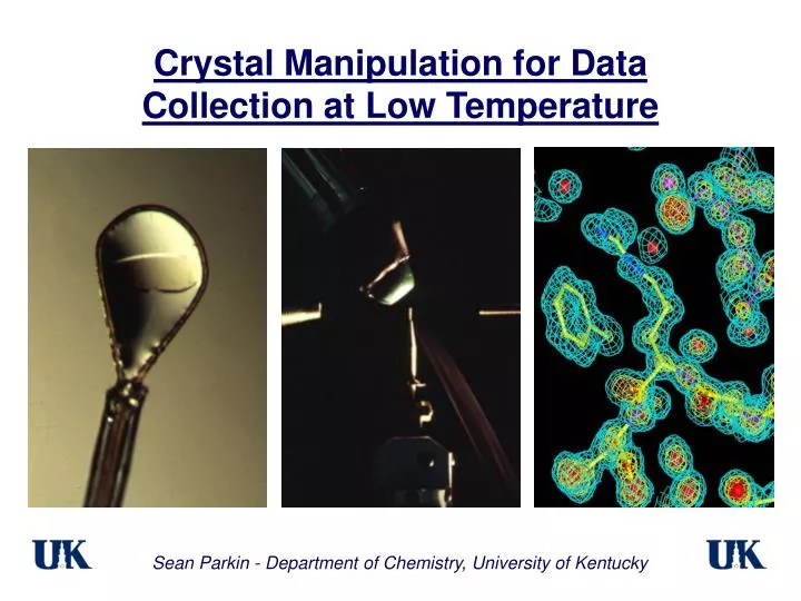
Crystal Manipulation for Data Collection at Low Temperature. Sean Parkin - Department of Chemistry, University of Kentucky. Benefits of low temperature Crystal treatment prior to cooling Cooling methods and cryogens Crystal mounting etc . Potential problems Annealing methods

E N D
Crystal Manipulation for Data Collection at Low Temperature Sean Parkin - Department of Chemistry, University of Kentucky
Benefits of low temperature • Crystal treatment prior to cooling • Cooling methods and cryogens • Crystal mounting etc. • Potential problems • Annealing methods • When nothing seems to work …
Benefits of Low Temperature Reduced radiation damage i) Primary – dose dependent ii) Secondary – time dependent iii) Thermal damage Decreased thermal motion (& disorder) iv) Improved resolution limit v) Possibility of disorder resolution vi) Sharper electron density Increased crystal lifetime Full data collection for most structures can be done on one single crystal.
Intensity decay from radiation damage Haas & Rossmann (1970) Acta Cryst.B26, 998–1004
Visible damage and reduced resolution Lysozyme diffraction at 100K before and after ~22 minutes on beamline 14-BM-C at APS Teng & Moffat (2000) J. Synch. Rad. 7, 313-317
Primary damage is dose dependent J J J J––––>J J K L J J J Jx-raysL LJ J J J J J––––>J J J L J J J J––––>J J K J Some molecules become chemically altered so the average electron density gets smeared. Primary radiation damage to H2O produces •OH radicals that can initiate further damage via secondary events Low temperature has little or no effect on primary damage.
Secondary damage is time (and dose) dependent J J K L ––––> J ) K µ L L J J x-rays L L J J J J J L time [JJL J J K J ––––> JJKJ A cascade of free-radical initiated reactions destroys long-range order even more, further smearing the electron density which increasingly destroys the high resolution data Low temperature can inhibit secondary damage
Thermal damage from very intense sources* J J KL––––>J)Kµ LL J JintenseL LJ J J J J Lx-rays[JJ L J J K J––––>J N KJ X-ray absorption dumps energy into the crystal Heating accelerates secondary damage Non-uniform heating causes temperature gradients and stress-induced damage A consideration on insertion device beamlines at third generation sources. All modes of damage will compound each other *e.g. Teng & Moffat (2000) J. Synch. Rad. 7, 313-317
Improvement of resolution I µ Ioexp{-2B(sinq/l)2} T1 = 300 K T2 = 100 K, Bo = 5 Å2 b = 0.05 Å2K-1 assume B(T) ≈ Bo + bT (Bo + bT1)/r12 = (Bo + bT2)/r22 r2 = r1 {(Bo + bT2)/(Bo + bT1)}1/2 Roughly three times as much data at 100K vs 300K Hope, H. (1988) Acta Cryst.B44, 22-26.
Reduced thermal motion General reduction in refined B values. Dramatic reduction may indicate resolved disorder. BPTI, main chain BPTI, side chains Parkin & Hope (1996) Acta Cryst.D52, 18-29.
Resolved disorder in favourable cases BPTI C-terminus, 298K BPTI C-terminus, 125K Parkin & Hope (1996) Acta Cryst.D52, 18-29.
Other benefits: Full datasets are usually obtained from just one crystal. For MAD data especially, systematic errors are minimized. Crystals can be harvested and stored. Important if crystals degrade, e.g. oxidization of Se-Met. Crystal mounting can be much less damaging to crystals … because of reduced amount of manipulation.
Benefits of low temperature • Crystal treatment prior to cooling • Cooling methods and cryogens • Crystal mounting etc. • Potential problems • Annealing methods • When nothing seems to work …
Prior to cooling the crystal i) Find a suitable cryoprotectant Paratone oil, mineral oil, polyfluoroethers ~60% success rate Remove surface water oils PEG < 4K : increase PEG, add other small PEGs PEG > 4K : add small PEGs MPD : increase MPD concentration Salt: add MPD/glycerol or even more salt ? exchange salt e.g. to sodium formate n.b. low salt requires more help than high salt Modify surface water antifreezes Small organics can bind at active sites - not good !
Finding a suitable cryoprotectant Elspeth Garman’s table of minimum amounts of glycerol needed to prevent ice formation in Hampton Screen I. These were arrived at by dilution rather than by replacement of water, so the numbers should be used with caution. Mitchell & Garman (1996) J. Appl. Cryst. 29, 584–585
Finding a suitable cryoprotectant Structures in Acta Cryst. D57, 2001. Garman & Doublié (2003) Meth. Enzymol. 368, 188-216.
Finding a suitable cryoprotectant Structures in Acta Cryst D56-57, 2000-2001. Garman & Doublié (2003) Meth. Enzymol. 368, 188-216.
Finding a suitable cryoprotectant Garman (1999) Acta Cryst.D55, 1641–1653
Prior to cooling the crystal ii) Optimize concentration of antifreeze The minimum required to suppress ice is not necessarily the optimum amount Mitchell & Garman (1994) J. Appl. Cryst. 27, 1070–1074
Prior to cooling the crystal iii) Introduction of antifreeze Single or multi-step soak / wash Sequential partial exchange of mother liquor Dialysis iv) Length of soak / wash Seconds to wash, minutes (hours ?) to soak a) Move crystal between solutions b) Solution pipetted onto crystal 40 40 30 30 % cryo-solution % cryo-solution 20 20 10 10 0 0 0 1 2 3 4 5 0 1 2 3 4 5 Time (minutes) Time (minutes) The goal has been to minimize the shock to the crystal Generally little optimization done unless there are real problems Garman (1999) Acta Cryst D55, 1641-1653
Benefits of low temperature • Crystal treatment prior to cooling • Cooling methods and cryogens • Crystal mounting etc. • Potential problems • Annealing methods • When nothing seems to work …
Cooling methods - cryogen characteristics Variable temperature is easy Very controllable Single step EASY Stream cool Fixed temp., 77 K Very controllable Two steps EASY LN2 dunk Harder Several steps Variable temp. possible but tricky Not easy to control without practice Propane dunk
Cooling methods - cryogen cooling rates N2 stream liquid N2 liquid propane N2 stream liquid N2 liquid propane Teng & Moffat (1998) J. Appl. Cryst. 31, 252–257 Walker, Moreno & Hope (1998) J. Appl. Cryst. 31, 954–956
Cooling methods – points to consider Cooling rate is proportional to DT ii) Liquid propane can be dangerous around potential sources of ignition iii) Due to inherent complexity, liquid propane methods are the hardest to make reproducible iv) Leidenfrost gas layer insulation of large objects is insignificant with ordinary-sized crystals v) Liquid propane has a large liquid range - constant stirring is required for reproducibility Make the process as simple as possible
Benefits of low temperature • Crystal treatment prior to cooling • Cooling methods and cryogens • Crystal mounting etc. • Potential problems • Annealing methods • When nothing seems to work …
Crystal mounting – tools loops - homemade arcs tongs loops - bought vials and holders special vials Pictures: Hampton Research; Bruker-Nonius; Sean Parkin
Crystal mounting – aqueous film removal under oil Aqueous films clinging to the crystal can often be teased away with a needle point. Or they may be wicked away with a wedge of pre-moistened filter paper. Most dry oils will accept a little water so small amounts will diffuse into the oil. This may be good or it may be bad.
Crystal mounting – manipulations in the dewar 1) Pre-cool tongs, plunge crystal. 2) Clasp the mounting pin. 3) Remove the pin holder. 4) Carry it to diffractometer. Parkin & Hope (1998) J. Appl. Cryst. 31, 945-953.
Crystal mounting - Tongs … transfer to diffractometer takes a couple of seconds … … open the tongs so that the cold stream blows in the gap.
Crystal mounting - Cryovials Note the inverted f axis … … means no cryogen spillage. pictures courtesy of MSC
Crystal mounting - robots SSRL Automated Fast Reproducible Expensive BruNo MSC - Actor pictures courtesy of MSC, SSRL, Bruker-AXS
Benefits of low temperature • Crystal treatment prior to cooling • Cooling methods and cryogens • Crystal mounting etc. • Potential problems • Annealing methods • When nothing seems to work …
Crystal environment should be controlled so that it is reproducible. Potential problems: Control and reproducibility Temperature versus time for a "crystal" held in stainless steel block tongs. Warming rate is about 0.5° per second (depends on tongs) Parkin & Hope (1998) J. Appl. Cryst. 31, 945-953
Potential problems: Control and reproducibility Ensure the crystal temperature is controlled throughout mounting and that it is reproducible. mount temp. dismount temp. Temperature vs time during mount / dismount Parkin & Hope (1998) J. Appl. Cryst. 31, 945-953
Potential problems: Ice Ice caused by inadequate cryoprotectant. Solution: optimize concentration Ice caused by snow from slushy liquid nitrogen sticking to the drop. Solution: carefully remount from fresh cryogen, gently tease off the snow etc. Pictures: Elspeth Garman (Oxford University)
More ice problems 1 2 3 A poorly positioned nozzle or draughts will cause snow to grow on the pin end. This can get serious if left too long. Pictures: (1) Sean Parkin; (2,3) Elspeth Garman (Oxford University)
Potential problems: Ice prevention Even in humid environments ice can be prevented without elaborate contraptions. • The important point is a well-defined geometric relationship between cold stream, mounting pin and goniometer head and to rigorously exclude draughts • Pin design • Cold stream geometry • Turbulence • Exclude draughts Parkin & Hope (1998) J. Appl. Cryst. 31, 945-953.
Potential problems: Mosaic spread Minimize mosaic spread to optimise data quality. It should prove possible to approximate the mosaicity of crystals at room temperature. Therefore it helps to know what this is ! Garman, E. (1999) Acta. Cryst. D55, 1641-1653. Dauter, Z. (1999) Acta. Cryst. D55, 1703-1717.
Potential problems: maximize cooling rate 1) Keep cryogen close at hand 2) Go for a large surface area to volume ratio - so small crystals have an advantage. Generally, S/V > 12mm-1 e.g. 0.4mm x 0.4mm x 0.4mm block, S/V = 15mm-1 0.5mm x 0.5mm x 0.5mm block, S/V = 10mm-1 0.4mm x 0.5mm x 0.2mm block, S/V = 19mm-1 Thus a plate should cool faster than a rod or a block.
Things to consider Be in control throughout the experiment The bare minimum antifreeze concentration needed to suppress ice formation is probably not the optimum amount for minimizing mosaic spread and maximizing resolution. Minimize crystal handling. Smaller crystals are easier to cool evenly. Attempt some sort of annealing (next). Make the mounting and retrieval process as simple as possible, but not simpler Simplicity leads to reproducibility
Benefits of low temperature • Crystal treatment prior to cooling • Cooling methods and cryogens • Crystal mounting etc. • Potential problems • Annealing methods • When nothing seems to work …
Annealing of macromolecular crystals Quick and (hopefully not so) dirty approaches Macromolecular Crystal Annealing Flash Annealing Systematic approaches Controlled slow annealing Controlled flash annealing
1) "Macromolecular Crystal Annealing" - procedure Crystal is quickly removed … … placed in cryoprotectant … … and then re-flash cooled. … for ~ three minutes … Harp, Timm, & Bunick, (1998) Acta Cryst. D54 622-628
Macromolecular Crystal Annealing Increased resolution and better mosaicity for nucleosome core particle crystal after 3 minute anneal in antifreeze or oil Harp, Timm, & Bunick, (1998) Acta Cryst. D54 622-628
Macromolecular Crystal Annealing A flash-cooled crystal of Patatin gave diffraction to 3.7 Å clearly showing multiple lattices. On annealing it broke into two pieces. On remounting, the larger piece diffracted to ~2.3 Å. Hansen, Harp, & Bunick, (2003) Meth. Enzymol. 368, 217-235
Macromolecular Crystal Annealing An otherwise trashed nucleosome core particle crystal resurrected after a 3 minute anneal Harp, Timm, & Bunick, (1998) Acta Cryst. D54 622-628
2) "Flash Annealing" - procedure Flash cooled … … stream diverted … … re-flash cooled. The cold stream blowing over the flash cooled crystal is blocked for a short period of time (seconds) until it has thawed. Then the obstruction is released to re-cool the crystal. Yeh & Hol (1998) Acta Cryst. D54, 479-480
Flash annealing - results Glycerol kinase, resolution limit ~4 Å, poor mosaic spread. Flash annealing by blocking the cold stream for 1.5 - 2 seconds three times gives ~2.8 Å resolution and better mosaic spread. Yeh & Hol (1998) Acta Cryst. D54, 479-480
Controlled annealing without thawing Accomplished in two ways: Slow warming using a controllable stream heater. Rapid warming to some pre-determined temperature by either dynamic mixing of cold and warm streams or by rapid switching of two cold gas streams. Questions to be answered: Is it a protein or a bulk water phenomenon ? How does annealing work ? Why does annealing work ? What are the mechanisms of protein crystal annealing ?