Download
1 / 44
440 likes | 589 Views
PARABOLIC RUNS. "Parabolic" flows are those which are:- - steady state flows; - predominantly in one direction, defined as that in which the velocity vector nowhere has a negative component; and - without recirculation or diffusion effects in that direction .

E N D
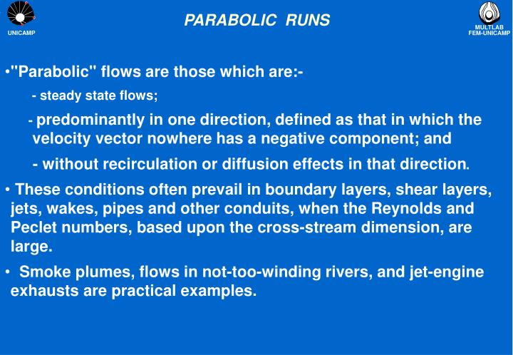
PARABOLIC RUNS • "Parabolic" flows are those which are:- - steady state flows; - predominantly in one direction, defined as that in which the velocity vector nowhere has a negative component; and - without recirculation or diffusion effects in that direction. • These conditions often prevail in boundary layers, shear layers, jets, wakes, pipes and other conduits, when the Reynolds and Peclet numbers, based upon the cross-stream dimension, are large. • Smoke plumes, flows in not-too-winding rivers, and jet-engine exhausts are practical examples.
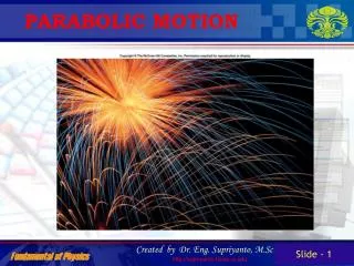
ESCOAMENTO ELÍPTICOrecirculação presente, mais de uma direção predominante
ESCOAMENTO ELÍPTICOrecirculação presente, mais de uma direção predominante
PARABOLIC FLOW • Such flows are called parabolic because mathematicians have applied that adjective to the differential equations which describe them, contrasting them with the related but different "elliptic" and "hyperbolic" ones. • The main reason for distinquishing parabolic flows from elliptic ones is that their special features may be exploited so as to reduce greatly the time and expense of the calculations.
MATHEMATICAL SIMPLIFICATION For 2D (yz) flows, the gradient on the transversal direction is much greater than the gradient along the main flow direction, the transport equation reduces to: Consequences: • W needs two b.c. in y and just one b.c. in z direction, V needs just one b.c. in y direction • V lost one equation, it just satisfies continuity, W can not match any open end along z direction, just inlets. • The order of the PDE has been reduced!
FINITE VOLUME EQUATIONS The finite-volume equations for parabolic problems differ from the general ones in three respects. • The first is that the terms in the finite-domain equations involving the coefficient aH are omitted. • In parabolic calculations, the terms expressing variations with time are also absent; so the general equation reduces to the following form when PARAB=T:
FINITE VOLUME EQUATIONS (cont.) • The second difference is the omission of the diffusive component from the coefficient aL that connects the current z step to the preceding one; so this term carries the convective contribution only. • The third difference concerns the representation of the pressure force on the z-directed velocity resolute w. The z-wise variations of pressure level, p, are decoupled from the lateral (ie x and y) variation of the pressures (which continue to be determined by reference to cell-wise continuity, see fully developed flows). • The force on the w velocities is taken as -Dp/Dz. In confined flows, EARTH determines p by reference to slab-wise mass continuity at each z; in unconfined flows, p has to be defined in some other way (see IPARAB and pbar).
INTEGRATION PROCEDURE • In PHOENICS, the predominant direction of a parabolic flow is always the z-direction. • Because of the absence of the AH term, a single sweep through the integration domain suffices. However, in order that the non- linearity and inter-connectedness of the equations can be adequately represented, sufficient iteration must be conducted at each slab, in order that imbalances in the equations have been adequately reduced; for single-sweep parabolic calculations allow no 'second chance'. • Therefore, instead of the LSWEEP = 50 (say) which is set for an elliptic-flow problem, the corresponding setting in a parabolic-flow calcultion would be LITHYD = 50 .
STORAGE IMPLICATIONS • To make one forward step in the integration sweep, it is necessary to hold in computer memory the variables relating to only two slabs: the local one, and its immediately-upstream neighbour. • This means that an unlimited number of slabs can be employed without any any increase of computer storage. Very-fine-grid solution can be obtained because all available storage can be used for the cross-stream directions. • Consequences: storage is therefore provided only for the current and low slabs. Attempts in GROUND coding to access "high" values will therefore fail.
VR SETTINGS • Models -> parabolic • Parabolic mode -> confined (pipe flows) unconfined (external pressure grad =0) unconfined Y (external press. Grad not 0) • External Pressure -> PBAR sets the external pressure for IZ=1
VR SETTING - GRID MATTERS • AZYV....determines the variation of YVLAST with z distance. This feature is for use in parabolic calculations ( see PARAB ) to enlarge the Y extent of the grid with downstream location so as to permit the capture of the lateral growth of jets, boundary layers, wakes and the like. • AZYV, when not equal to 0.0 (its default value), effects a variation of the Y-direction extent of the grid, i.e. of YVLAST, with variation of distance z. The cumulative effect of this is an approximate power-law growth, • When AZYV is set to 1.0, this gives a linear growth of the x-grid width in the z direction, of slope equal to: (YVLAST at inlet)/ZWADD) . Hence, for a desired slope, set ZWADD equal to YVLAST at inlet divided by the slope.
VR SETTING - GRID MATTERS Y Z • A distorted grid (BFC) is generated to follow the growth rate of the boundary layer. • The solved variables are W1 and V1 but the output displays the projections of the resultant velocities along the Y and Z directions by means of VCRT and WCRT
BOUNDARY CONDITIONS • Since, by definition, downstream events can have no upstream influence in a parabolic situation, no downstream boundary conditions are needed. Moreover, attempts to provide them may have undesirable effects, because PHOENICS will attempt to apply them at the last slab that it knows about, which is the current one. • INLET conditions are necessary because it defines the ‘previous’ slab to start the marching process. • The NORTH and SOUTH boundaries are necessary to specify f values.
BOUNDARY CONDITIONS NORTH INLET SOUTH
SOME CLUES ON PHOTON & AUTOPLOT • If IDISPA=1, then PARPHI and PARXYZ files are generated. Type PARPHI on PHOTON file box. The PARXYZ will be automatically picked up. • For AUTOPLOT, rename PARXYZ file to XYZ file. At the comand FILE type PARPHI 5, it will pick up automatically the XYZ file. • For monitoring convergence make IZMON = 1 if you want to monitor every slab. If IZMON = 5 it will display the residues only every 5 slabs.
WORKSHOP: BLASIUS PROBLEM This run shows what happens in a boundary-layer flow adjacent to a heated wall. An expanding grid is used in the direction normal to the wall so as to match the growth of the boundary layer. Fixed, zero pressure boundary. W=1.0m/s, P = 0 N/m2 Prescribed: - - - - - - - - - - - - - - - - - - - - - - - - - - - - - - - - - - - - - - - mass inflow rate, -----> -----> -----> velocity -----> ----> ----> and -----> ---> --> enthalpy ______________________________________________ ^ ///////////////////////////////////////////////////////////////////////////////////////////// y| Wall |---> z
WORKSHOP #1 SETTINGS SIZE: 0.04 M (YVLAST) & 2.0 M (ZWLAST) GRID: NY = 20 and NZ = 28 UNIFORME MODEL: PARABOLIC & UNCONFINED, PBAR = 0 DOMAIN PROPERTIES: PRPS = 0 (Air 20C), WIN = 1.0 m/s BOUNDARIES: INLET, OUTLET (NORTH), PLATE (SOUTH) NUMERICS: LHITD=500; RELAX P1=-1.0;V1 and W1 = 10 TYPE ON Q1: IDISPA=1 Run and compare against analytic solution the velocity profiles at z=1.5 m (IZ = 21). Use AUTOPLOT
ANALITYCAL BLASIUS SOLUTION Blasius vel profile for Z = 1.5 m, Y (m) and W (m/s) IY W1 6.801E-04 4.696E-02 1.360E-03 9.391E-02 2.040E-03 1.408E-01 2.721E-03 1.876E-01 3.401E-03 2.342E-01 4.761E-03 3.265E-01 6.801E-03 4.606E-01 9.522E-03 6.244E-01 1.224E-02 7.611E-01 1.360E-02 8.167E-01 1.632E-02 9.011E-01 1.904E-02 9.529E-01 2.312E-02 9.880E-01 2.721E-02 9.978E-01 Table File for AUTOPLOT: type (2) • One can create using ASCII file format (notepad, fortran editor, etc) • It is espected labels on the first line • Make sure that the file type is the same of the q1 or result files. • Download Blasius data for this problem: blasius • Download q1 for wksh#1
WORKSHOP #2 SETTINGS Investigate the use of a better grid. Keep the same settings from wksh#1, but use non-uniform grid GRID: NY = 20 power = 1.5 NZ = 28 power = 1.5 Run and compare against analytic solution the velocity profiles at z=1.5 m (IZ = 23). Use AUTOPLOT
WORKSHOP #3 SETTINGS Insert the Energy Equation using temperature Keep the same settings from wksh#2. The inlet temperature is 20oC and the plate surface is at 100oC. Do not forget to STORE(PRPS) when using TEM1 as solved variable. Run PHOTON to observe the temperature profile.
WORKSHOP #4 SETTINGS Investigate the use of distorted grid. Keep the same settings from wksh#1, but use distorted grid: SIZE: YVLAST = 0.008 m GRID: NY = 20 power 1.5, and NZ = 28 power 3.0; AZVY = 0.5; ZWADD = 1.6 Run and compare against analytic solution the velocity profiles at z = 1.5 m (IZ = 23). Use AUTOPLOT Remark: there must be a BUG when distorted grid is in use. The V1 velocity gives negative values!
OUTPUT WKSH#4 There must be a BUG with the solver and or implementation. The tranversal velocity V1 must be positive. The distorted grid gives up a negative V1!
WORKSHOP #5 SETTINGS - THE WALL JET FIXED PRESSURE (FREE BOUNDARY) WIN2 = 0.01 TIN2 = 20 NY2=10 YVLAST2 = 0.03 WIN2 = 1.00 TIN1=100 NY1=15 YVLAST2 = 0.01 SWALL NZ = 28 POWER = 1.5 ZWLAST2 = 2.00 • A wall jet is formed when a jet is discharged close to a wall while its other boundary is free to atmosphere. • From a ‘fresh’ q1, set up a finite volume model of an air wall jet according to the schematic below
BLASIUS TALK=F; RUN( 1, 1) IRUNN = 1 ;LIBREF = 0 ************************************************************ Group 1. Run Title TEXT(LAMINAR B.L. (2) ) REAL(WIN,SLOPE) SLOPE = 1./2. * define the slope WIN=1.0 * define the inlet velocity ************************************************************ Group 2. Transience STEADY = T ************************************************************ Groups 3, 4, 5 Grid Information YVLAST=0.002; ZWLAST=1.0 * define the domain extension along Y and Z directions NY=8;NZ=12 * define the number of volumes in each direction GRDPWR(Y,NY,YVLAST,1) * creates an uniform grid GRDPWR(Z,NZ,ZWLAST,1) CARTES=T
BLASIUS Group 6. Body-Fitted coordinates ************************************************************ * Parabolic simulation PARAB = T * says the model is parabolic AZYV = 0.5 * sets the grid growth rate along Y direction ZWADD = YVLAST/SLOPE ************************************************************ Group 7. Variables: STOREd,SOLVEd,NAMEd ONEPHS = T NAME( 1) =P1 ;NAME( 5) =V1 NAME( 7) =W1 * Y in SOLUTN argument list denotes: * 1-stored 2-solved 3-whole-field * 4-point-by-point 5-explicit 6-harmonic averaging SOLUTN(P1 ,Y,Y,N,N,N,Y) SOLUTN(V1 ,Y,Y,N,N,N,Y) SOLUTN(W1 ,Y,Y,N,N,N,Y)
BLASIUS Group 8. Terms & Devices * Y in TERMS argument list denotes: * 1-built-in source 2-convection 3-diffusion 4-transient * 5-first phase variable 6-interphase transport TERMS (P1 ,Y,Y,Y,N,Y,N) TERMS (V1 ,Y,Y,Y,N,Y,N) TERMS (W1 ,Y,Y,Y,N,Y,N) DIFCUT = 0.000000E+00 ;ZDIFAC = 1.000000E+00 GALA = F ;ADDDIF = F ISOLX = 0 ;ISOLY = -1 ;ISOLZ = 0 ************************************************************ Group 9. Properties RHO1 = 1.189000E+00 ENUL = 1.544000E-05 ************************************************************
BLASIUS Group 13. Boundary & Special Sources No PATCHes used for this Group PATCH(IN,LOW,1,1,1,NY,1,1,1,1) * sets the inlet condition COVAL(IN,P1,FIXFLU,RHO1*WIN) COVAL(IN,W1,FIXVAL,WIN) PATCH(BOUN,NORTH,1,1,NY,NY,1,NZ,1,1) * sets north boundary, const. pressure COVAL(BOUN, P1, 10000, PBAR) COVAL(BOUN, W1 , 0, WIN) PATCH(WALL,SWALL,1,1,1,1,1,NZ,1,1) * sets south boundary, wall COVAL(WALL, W1, 1, 0) COVAL(WALL, V1, 1, 0) EGWF = T ************************************************************ Group 14. Downstream Pressure For PARAB IPARAB = 1 * sets for unconfined flow the parabolic model AZPH = 0.000000E+00 ;PBAR = 0.000000E+00
BLASIUS Group 15. Terminate Sweeps LSWEEP = 1 LITHYD = 500 * sets for 500 iterations for slab SELREF = F RESREF(P1)=5.0E-6 RESREF(W1)=1.8E-06 RESREF(V1)=4.7E-07 ************************************************************ Group 17. Relaxation RELAX(P1 ,LINRLX, 1.000000E+00) RELAX(V1 ,FALSDT, 1.000000E+01) RELAX(W1 ,FALSDT, 1.000000E+01) ************************************************************ Group 24. Dumps For Restarts NOWIPE = T IDISPA = 1 ;IDISPB = 0 ;IDISPC = 0 * writes the result of each slab on PARPHI file
BIBLIOGRAPHY • ENCYCLOPEDIA -> PARABOLIC FLOWS • Minkowycz, W.J., “Handbook of Numerical Heat Transfer”, Wiley Intersci. 1988 • Patankar S. and Spalding, D.B., “A calculation procedure for heat, mass and momentum transfer in three dimensional parabolic flows”, Int. J. Heat Mass Transfer, vol15, pp. 1787-1806, (1972) • V.S.Pratap and Spalding, D.B., “Fluid flow and heat transfer in three dimensional duct flows’, Int. J. Heat Mass Transfer, vol19, pp. 1183-1188, (1976) • Patankar S., Rafiinejad, D. and Spalding, D.B, “Calculation of the three dimensional boundary layer with solution of all three momentum equations”, Comp. Methods in applied Mechanics and Engng, vol 6, pp. 283-292, (1975)
AZXU & AZYV ------ Real; default= 0.0; group 3 --- Satellite Help - • AZXU....determines the variation of XULAST with z distance. This feature is for use in parabolic calculations ( see PARAB ) to enlarge the x extent of the grid with downstream location so as to permit the capture of the lateral growth of jets, boundary layers, wakes and the like. • AZXU, when not equal to 0.0 (its default value), effects a variation of the x-direction extent of the grid, i.e. of XULAST, with variation of distance z. When AZXU is set to a constant other than GRND, XULAST is multiplied at each z-direction step by the factor:(1.0 + AZXU*DZ/(ZWADD+Z)) . The cumulative effect of this is an approximate power-law growth, XULAST/(XULAST at inlet) = (1.0+ZW/ZWADD)**AZXU , where ZW is the z-coordinate of the current z step. • When AZXU is set to 1.0, this gives a linear growth of the x-grid width in the z direction, of slope equal to: ((XULAST at inlet)/ZWADD) . Hence, for a desired slope, set ZWADD equal to XULAST at inlet divided by the slope. • If AZXU is set to GRND, it causes EARTH to visit GROUP 3 of GROUND where XRAT is to be set as the factor which will multiply XULAST.
AZDZ • ------ Real; default= 0.0; group 5 --- Satellite Help - • AZDZ....determines the variation of DZ with z distance. • AZDZ is used, especially in parabolic calculations, for changing the z-direction step size, DZ. If AZDZ is given any constant value other than GRND, the step size is multiplied by the factor (1.0 + AZDZ) at each forward step. The step size so multiplied is always the nominal one which has been set by the SATELLITE (via GRDPWR, or by direct settings of the ZFRAC array elements). • When AZDZ is set equal to GRND, EARTH will expect to find a direct setting of DZ in GROUP 5 of GROUND.
AZPH • ------ Real; default=0.0; group 14 ---- Satellite Help - • AZPH....linear coefficient for the downstream impressed pressure level PBAR . • AZPH (P stands for pressure, and H for high) is a quantity which may be useful in parabolic runs for which IPARAB is set greater than zero; for these are the ones for which the downstream (i.e. high) pressure is set by the user. If AZPH is set to a constant, other than GRND, the downstream pressure will exceed the current-slab pressure by the amount AZPH * DZ. If, however, AZPH is set equal to GRND, EARTH will visit GROUP 14 of GROUND in order to pick up a value of PBAR, which will then be used as the downstream pressure.
PBAR • ------ Real; default= 0.0; group 14 -- Satellite Help - • PBAR....downstream mean pressure for use in parabolic calculations, ie. PARAB=T. If IPARAB=0, as in confined flows, the downstream pressure at each z slab is computed by EARTH; but, if IPARAB=1, as in unconfined flows, the user must prescribe the downstream pressure via PBAR. • If the unconfined flow is one of zero pressure gradient, then PBAR may simply retain its default setting of 0.0. However, if a z-wise variation of impressed pressure needs to be prescribed, then the user must set PBAR in the Q1 file to the required pressure level of the first slab, and then the downstream pressure at each z slab must be set via AZPH as explained under the entry AZPH. • In addition to prescribing the downstream pressure level, the user must also prescribe velocity boundary conditions at the free boundaries of the current forward step that are consistent with the prescribed variation of PBAR; thus, the pressure and the longitudinal velocity should obey the Bernoulli relation: • P + 0.5*rho*w**2/2 = constant
PBAR • For example, consider the case of a y-z boundary-layer calculation over a flat plate on the south boundary, and in which the North boundary is a free stream with an axial velocity which increases linearly with z. For this situation of a boundary layer in a favourable pressure-gradient the user would set the following PIL commands in the Q1 file: • IPARAB =1 which means that the downstream pressure PBAR must be prescribed by the user. • AZPH =GRND which means that the downstream pressure PBAR must be set by the user in Group 14 of GROUND for each z slab. • PBAR =0.0 which defines the pressure level for the first z slab.
PBAR • In Group 14 of GROUND the user would insert the following coding to define the downstream pressure: • GWFRE=ZW+GZ0 • PBAR=PTOT0-0.5*RHO1*GWFRE*GWFRE • where: • GWFRE is the free-stream velocity; • GZ0 is the user-specified virtual origin; • ZW is the z-location of high face of the current z-slab; • RHO1 is the fluid density; and • PTOT0 is the user-specified free-stream total pressure
PBAR • The foregoing settings must be reinforced by appropriate free- stream boundary conditions at each z, thus in the Q1 file: • PATCH(FREE,NORTH,1,1,NY,NY,1,NZ,1,1)COVAL(FREE,P1,FIXP,0.0);COVAL(FREE,W1,ONLYMS,GRND) • The GRND value for W1 causes EARTH to visit Group 13 Section 12 of GROUND for a value for the cell at NY equal to the external velocity at the current IZ slab, as the following Fortran coding contrives: • IF(INDVAR.EQ.W1.AND.NPATCH(1:4).EQ.'FREE') THENL0VAL=L0F(VAL) F(VAL+NY)=ZW+GZ0 ENDIF • See the Encyclopaedia entry 'VAL' for the significance of the VAL index.
ZWADD • ----- Real; default=0.0; group 5 ----- Satellite Help - • ZWADD....Addition which is made to z-coordinate values when these are used for grid-stretching and other formulae in parabolic calculations. It permits the origin of the grid to be displaced from z=0.0, i.e. it locates the virtual origin. • See AZXU for more details.