Download
1 / 21
250 likes | 746 Views
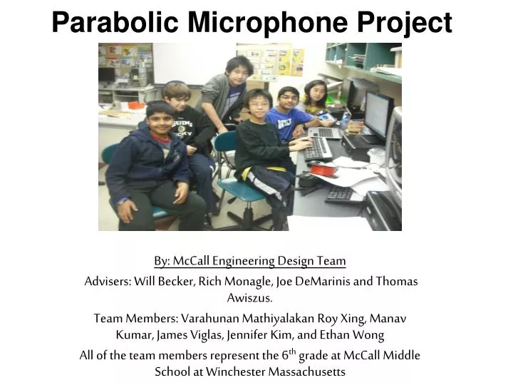
Parabolic Microphone Project. By: McCall Engineering Design Team Advisers: Will Becker, Rich Monagle, Joe DeMarinis and Thomas Awiszus. Team Members: Varahunan Mathiyalakan Roy Xing, Manav Kumar, James Viglas, Jennifer Kim, and Ethan Wong

E N D
Parabolic Microphone Project By: McCall Engineering Design Team Advisers: Will Becker, Rich Monagle, Joe DeMarinis and Thomas Awiszus. Team Members: Varahunan Mathiyalakan Roy Xing, Manav Kumar, James Viglas, Jennifer Kim, and Ethan Wong All of the team members represent the 6th grade at McCall Middle School at Winchester Massachusetts
The Purpose of This Contest The purpose of this contest was to engineer a good parabolic reflector for the New England Patriots.
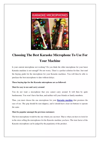
What is a Parabolic Microphone? It is a microphone mounted on a reflector that concentrates and focuses the sound. Think of it as an Audio Telescope
How does it work? A Parabolic reflector will focus all incoming sound onto a single point. Because the incoming waves are intercepted by a large area, they are highly concentrated at the focal point.
What is a Parabola? • It is a curve generated by the formula Y = X2/ 4f, Where f = the location of the FOCUS point • If you spin a parabola about its center axis, you generate • a parabolic surface that can be used as a reflector.
Why Not Use a Spherical Reflector? A spherical reflector, is easier to build but it does not nearly produce the same amount of quality as a parabolic reflector because the sound is not focused at one specific point but a parabolic reflector does.
Comparing a Parabola to a Circle As you can see, the curve of a Parabola and circle differentiate after (10,20) and (-10,2). The dimensions are in inches
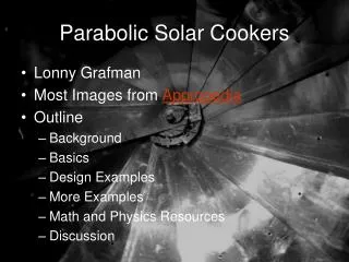
How to Construct the Reflector By breaking it down into segments. We can cut the segments from flat, stiff cardboard, then bend them and piece them together to form a Parabolic dish. A web site that explains all this is: http://veone.virgin.net/LSMA.mal/var/parabola.htm
How we constructed a segment This is the basic layout math. More details will come. The spacing between folds is not uniform. The edges are not straight lines.
The spacing between folds change because the surface is tilted But don’t worry, Microsoft Excel can help us to calculate all this without a lot of work.
The Parabola Dimensions that we used This is the Excel Calculation for laying out the segments Use centimeters for the last two columns.
Shape of Edges Explanation for Edge Curve: First, the edge is not straight because if it was, the 12 segments would not fit together. If you have some gaps in between the segments then when you curve them, they will fit together. This is where the VD comes in If you want to know why Tangent 15 then the answer is simple. You divide 360 degrees by x segments (in this case 12) and you get 300. But you need to make a right triangle so you divide the segment in half and you get 150 so that explains tan 15. Formula: Tan15 times (3 times x inches)
The Distance between Bends The parabolic curve between bends is like a right triangle and once you find the x+y coordinates(x2/4*focus) you have two legs of the right triangle. Using the Pythagorean Theorem, we can figure out the hypotenuse of the segments and one by one and eventually get the 3-Dinensional Parabolic Curve
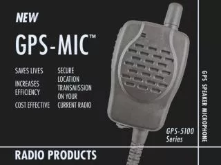
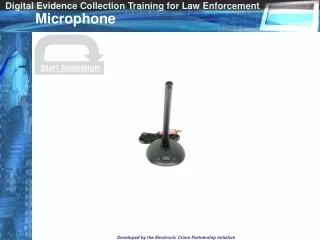
The Inter-workings Electrostatic Microphone • An Electrostatic microphone consists of a thin, electrically charged membrane that is close to a metal pickup plate or grid. Vibrations of the membrane create an electrical signal on the plate. • Electrostatic mikes also contain a transistor as an integral part of the tiny capsule. • These are much more sensitive than Dynamic microphones.
Research and Selecting Solutions A Parabolic Microphone is a reflector that accepts energy and then it concentrates it all at a single focal point that then greatly increasing the intensity of it. To study this, we went on a website to study about the math and science of the Parabolic Microphone ( First Citation) We considered many different materials for the Parabolic Microphone until we came across a material that suited our needs: Cardboard: We chose Cardboard because it was cheap and easy to work with.
Purpose and Selecting Solutions Part 2. Cardboard in its original form is a very poor reflector but we researched different materials that hardened cardboard, we chose acrylic enamel and then we came across a construction based silicon glue and of course, an old classic: masking tape. The tape was reinforcing the tensile strength and the Construction based silicon glue reinforced the compressive strength. We also used wooden fixtures to keep the different segments of the curve standing. Then we researched different types of microphones. The main two types of microphones existing are Electrostatic and Dynamic mikes. We ended up going with the electrostatic because it captures more sound from more directions.
Construction- Part 1 • To construct the Parabolic Microphone, we had to start at the first step: building the template for the segments. We had a origin point and a small indent about every three inches. To find the sides of the triangle we to find the VD or distance from the origin and then mark the FC distance to the outside edge. • Next we cut the segments from a piece of regular cardboard. We cut a total of 12 segments. • We built a fixture to make sure the segments were in a parabolic curve and then we glued and taped them together. • Next, we cut circles from piece of scrap plywood to reinforce the back. • We next used a rotary saw to cut braces for the parabolic microphone and using a fixture, we made the segments were tightly interlocked.
Construction- Part 2 • Next we built a supporting beam for the microphone and supported it with wires • Next we cut four holes and then put the microphone in place. We used plastic ties so the microphone can move up and down.
Our Citations The McCall Engineering Design Team would like to thank; Mayes, Lawrence. "Make Big Paraboloid Reflectors Using Plane Segments." Instructions for Making Big Parabolic Reflectors. Lawrence Mayes, 15 Apr. 2006. Web. 23 Mar. 2012. <http://vzone.virgin.net/ljmayes.mal/var/parabola.htm>.