Download

1 / 39
390 likes | 566 Views
Optimization of Power Reduction in FPGA Interconnect by Charge Recycling. Deepa Soman , HyunSuk Nam, Rekha Srinivasaraghavan , Shashank Sivakumar. Agenda. Day 2 Power Reduction Techniques (Conti) Charge Recycling Our Project Discussions. Day 1 Intro Power Consumption Techniques

E N D
Optimization of Power Reduction in FPGA Interconnect by Charge Recycling DeepaSoman, HyunSuk Nam, RekhaSrinivasaraghavan, Shashank Sivakumar
Agenda • Day 2 • Power Reduction Techniques (Conti) • Charge Recycling • Our Project • Discussions • Day 1 • Intro • Power Consumption Techniques • Power Reduction Techniques • Discussions
Introduction • Motivation • Achilles’ Heel • Logic flexibility & re-programmability -longer wires • (7-14 X) higher than asics
Power Consumption • Dynamic Power - power consumed while the inputs are active • Static power - power consumed even when there is no circuit activity !!!
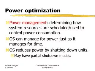
Hardware Techniques • Voltage Scaling Dual Vdd • Frequency Scaling • Clock Gating
Voltage Scaling • Selecting core voltage based on performance requirements • How to Choose? – From Timing Analysis • Types: • 1) Static Voltage Scaling • 2) Dynamic Voltage Scaling
1. Static Voltage Scaling • Selected core voltage only • Realized using on chip Low-Dropout regulator(LDO) • Voltage controlled by configuration bit stream • 0.8-V - minimum dynamic and leakage power • 1.0-V - overall highest performance 1.0v 0.8v LDO [1]"A FPGA Prototype Design Emphasis on Low Power Technique" Xu, Jian
2. Dynamic Voltage Scaling • Provides different voltage levels • Realized using voltage controlling unit • Can be level shifter or DC-DC converter DVS implementation (LDMC – Logic Delay Measurement Unit) Delay error ”Dynamic Voltage Scaling for Commercial FPGAs”, C.T. Chow1, L.S.M. Tsui1, P.H.W.
Dual Supply Voltage (Vdd) • Separate voltage supplies for configuration SRAM and other elements • Purpose: To support sleep mode • Shutdown most logic except SRAM using LDO “A Dual-VDD Low Power FPGA Architecture” A. Gayasen1, K. Lee1, N. Vijaykrishnan1, M. Kandemir1, M.J. Irwin1, and T. Tuan2
Performance • Static voltage scaling techniques leads to nearly 53% power reduction. Dynamic(upto 54%). Dual Vdd- 14% • Merits: • SVS - Simple hardware • DVS - Self adaptive • Dual Vdd – eliminate speed penalty • Demerits: • SVS - Voltage is fixed • DVS - design complexity • Dual Vdd - area overhead [1]"A FPGA Prototype Design Emphasis on Low Power Technique" Xu, Jian [2]”A 90-nm Low-Power FPGA for Battery-Powered Applications”,Tuan, Das, Steve, Sean
Frequency Scaling f : frequency of switching Simple dynamic clock management circuit (b) Using Feedback, PLL circuit can reduce skew; lock time (c) dynamic clock division • Merits: • Can subsequently reduce voltage • Demerits: • Increased Latency Dynamic Clock Management Implementations
Benefits of Frequency Scaling • As frequency decreases, power consumption also decreases "Dynamic Clock Management for Low Power Applications in FPGAs", Lan, zilic
Clock Gating • Controlling the clock flow • Purpose: To temporarily disable blocks • Can be realized in hardware using clock enable signals • minimizes power dissipation in clock circuits/network
Clock Gating - Performance Clock Power Reduction for Virtex-5 FPGAs Over 20% power reductions are observed for the DSP circuits • Eliminates unnecessary toggling on outputs, gates of FFs and clock signals industry-a,b,c,d, are DSP circuits, while the remaining circuits are collected from customers and are of unknown function • Demerits: • Clock skew "Clock Power Reduction for Virtex-5 FPGAs",Wang, Gupta, Anderson
SoftwareTechniques • System Level: • Algorithm Modification • CAD Tools : • Logic Partitioning • Mapping, • Clustering • Placement & Routing A
Low Power FFT Implementation • Architecture • Matrix multiplication ->1D array low power dissipation than 2D array • Module Disabling – Clock gating to disable modules eg: twiddle factor calculation dynamic memory activation • Multiple time multiplexed Pipeline uP • Parallel Processing • Algorithm : Block Matrix Multiplication
FFT implementation Results • 17% to 26% power reduction • "High throughput energy efficient multi-FFTarchitecture on FPGAs" , Chen , Park, Prasanna
Energy Reduction Contributions of CAD Stages • Clustering contributes to the major share ! "On the interaction between power aware FPGA CAD algorithms" , Julien , Steven
Power Aware Clustering • Power Aware TV pack • How?? • Cost function Modification to include power
Results: Power Aware clustering “Netlength Based Routability Driven Power Aware Clustering" , Akoglu, Easwaran
Results "On the interaction between power aware FPGA CAD algorithms" , Julien , Steven
Temperature Aware Routing • leakage current increases exponentially with temperature • Switching capacitance
Algorithm • By discouraging routing algorithm to form connections that cross hotspot regions • Cost Function Modification: • Power Savings Range between 30 – 63 % "A Temperature-Aware Placement and Routing targeting 3D FPGAs", Kostas, Soudris
Main/Baseline Paper • Problem Addressed • Power consumption in FPGAs • is dominated by • interconnect(62%) • Proposed idea • Charge recycling for • power reduction • in FPGA interconnect
Charge Recycling in FPGAs • How?? • “Unused routing resources “ as reservoirs • Reduces charge drawn from Vdd • 25% reduction in energy Unused/Reservoir Unused/Reservoir Unused w/o friends !!
CR-Capable FPGA Interconnect • Analysis Four components • SRAM Cell • Produce signals CR and TS : control a switch (Normal, CR, tri-state ) • Delay Line • Transition between VIN and DLOUT • CR Circuit • Perform the charge sharing between the load and reservoir • Input Stage
Experiments/Methodology • VPR6.0 • Baseline : Island style, Unidirectional, Wilton (K=6 ,N=4) • Router – Path Finder - Cost Function Modification • Post Routing CR mode • VPR place/route tool helps in • finding % increase in area
VPR Cost Function • Cost Function – Path Finder • Modified Cost Function
Post - Routing • Mixed Integer Linear Program • Tries to maximize the number of nodes to be put into CR mode • Constraint: Critical delay of the circuit
Results • Dynamic power in the FPGA interconnect is reduced by up to ∼15-18.4%
Results Continued… • Number of min-width transistors as the area metric • Reductions in power savings are not directly proportional to the reduction in CR-capable switches (area)
What we propose new? • Not all unused wires become friends • Unused wires connected to constant • voltage • “URekha” --- Unused wires Tri-stated • “further power savings!!” • ~6% savings