Download
1 / 11
110 likes | 247 Views
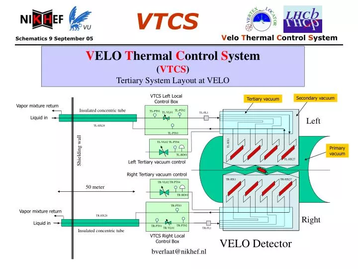
TL-PT04. TR-PT04. TL-VL02. TR-VL02. TL-BD01. TR-BD01. V ELO T hermal C ontrol S ystem ( VTCS ) Tertiary System Layout at VELO. VTCS Left Local Control Box. Secondary vacuum. Tertiary vacuum. Vapor mixture return. Insulated concentric tube. TL-PT02. TL-PT01. TL-VL01. TL-FL1.

E N D
TL-PT04 TR-PT04 TL-VL02 TR-VL02 TL-BD01 TR-BD01 VELO Thermal Control System (VTCS) Tertiary System Layout at VELO VTCS Left Local Control Box Secondary vacuum Tertiary vacuum Vapor mixture return Insulated concentric tube TL-PT02 TL-PT01 TL-VL01 TL-FL1 Liquid in Left TL-HX28 TL-PT03 TL-HX1 Primary vacuum Shielding wall TL-HX27 Left Tertiary vacuum control Right Tertiary vacuum control TR-HX1 TR-HX27 50 meter TR-PT03 Vapor mixture return TR-HX28 Right Liquid in TR-PT02 TR-PT01 TR-VL01 TR-FL1 Insulated concentric tube VTCS Right Local Control Box VELO Detector bverlaat@nikhef.nl
Tertiary VTCS schematics at RB84 plant Vapor mixture from concentric tube Liquid to concentric tube Liquid to concentric tube Vapor mixture from concentric tube TL-LT01 TR-LT01 TL-BD02 TR-PT06 TL-PT06 TR-BD02 TR-VL03 TL-VL03 TL-VL16 TR-VL16 TRL-VL18 SA-HX06 / TR-HX31 SA-HX05 / TL-HX31 TR-PT05 TL-PT05 TRL-VL17 SB-HX06 / TR-HX32 SB-HX05 / TL-HX32 TL-VL15 TR-VL15 TL-AC01 TR-AC01 TR-HT05 TL-HT05 TRL-VL12 TL-PT07 TR-PT07 TL-VL14 TR-VL14 TL-HT06 TR-HT06 TL-VL13 TR-VL13 TR-VL09 TL-VL09 SA-HX04 / TR-HX29 SB-HX03 / TL-HX30 TRL-VL11 TL-VL08 TR-VL08 SB-HX04 / TR-HX30 SA-HX03 / TL-HX29 TL-PM01 TR-PM01 TRL-PM01 TR-VL04 TL-VL04 TL-VL07 TR-VL07 TR-VL05 TL-VL06 TR-VL06 TL-VL05 TRL-VL10 Tertiary VTCS Left Detector (TL) Tertiary VTCS Right Detector (TR) bverlaat@nikhef.nl
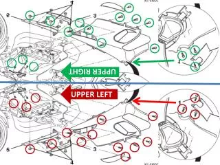
Temperature sensor labeling: (01) = Tx-TT01 (02) = Tx-TT02 …… (48) = Tx-TT48 8 x 50 pins Electrical Vacuum feed through connectors Type: #........... VTCS sensor and actuator overview per VELO half Tx-FL01 Tertiary vacuum (44) 4x Mounting Board (Capacity = 20x PT100 & 2x Heater (2A) per board Tx-BD01 (48) (47) (37) (36) Tx-PT02 Tx-PT04 Tertiary Vacuum Control Local Control Box Heater group Tx-HT01 (6x Watlow K010030c500000) Heater group Tx-HT03 (6x Watlow K010030c500000) Tx-VL02 Tx-PT03 Tx-PVL01 (46) (38) (40) Tx-PT01 CO2 in and outlet Tertiary vacuum connection to secondary vacuum (39) (45) (41) Electrical Connector Type: 6 pin LEMO (FGG.OB.306.CLAD52) Heater group Tx-HT04 (6x Watlow K010030c500000) Heater group Tx-HT02 (6x Watlow K010030c500000) (35) (32) (27) (24) (31) (28) Electrical Bulkhead Connector Type: 6 pin LEMO (EEG.OB.306.CLL) (33) (25) (29) (34) (26) (30) (22) (23) (20) (21) (19) (17) (18) (14) (15) (16) (13) (08) (09) (11) (12) (05) (06) (07) (10) (04) (02) (03) (01) TL-HX25 TL-HX26 TL-HX27 TL-HX9 TL-HX23 TL-HX19 TL-HX17 TL-HX22 TL-HX18 TL-HX20 TL-HX24 TL-HX10 TL-HX11 TL-HX15 TL-HX21 TL-HX12 TL-HX7 TL-HX13 TL-HX16 TL-HX14 TL-HX6 TL-HX8 TL-HX1 TL-HX2 TL-HX3 TL-HX4 TL-HX5 (43) (42) bverlaat@nikhef.nl Tx = TL for left detector half and TR for right detector half
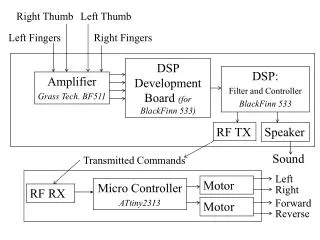
T-sensor signal wires P-sensor signal wires Heater power wires Installation direction VTCS control integration for 1 VELO half Cooling connector Connector onto Evaporator Evaporator Outdoor T-sensors to dummy rep. board Dummy repeater board Tertiary vacuum control VTCS local control box Evaporator into Module base 2x3 P-sensors Evaporator sensors to connector board 2x4 Heaters 2x48 T-sensors Heaters and T-sensors to connector board Module base Cooling plant and control on RB-84 platform Connection to bake-out control bverlaat@nikhef.nl RF-Box
VTCS Schematic at VELO VELO Cave (View from tunnel) Concentric Transfer tube VTCS Local control boxes VTCS Sensor boards (Dummy repeater) Removable tubing Right Evaporator Connection Left Evaporator Connection Right Detector Left Detector Tertiary Vacuum Control bverlaat@nikhef.nl
T-sensor signal wires P-sensor signal wires Heater power wires 4x P-sensors TxPT01-TxPT04 4x Shielded cables 6 wire SCEM 04.21.48.050.6 VTCS Local Control Box Dummy Repeater Board T-Sensor TxTT45-TxTT48 48x T-sensors TxTT01-TxTT48 4x Shielded cables 50 wire SCEM 04.21.51.350.0 37x T-Sensor TxTT01-TxTT37 7x T-Sensor TxTT38-TxTT44 T-Sensor TxTT38-TxTT44 4x Heater TxHT01-TxHT04 VTCS Cabling logic at VELO 4x Heater TxHT01-TxHT04 4x Shielded cables 4 wire SCEM 04.21.52.180.6 Quantities for 1 detector half bverlaat@nikhef.nl
Module base thermostatic heating schematics 48 Volt DC Watlow K010030c500000 52.3Ω, 15 Watt max Watlow K010030c500000 52.3Ω, 15 Watt max Watlow K010030c500000 52.3Ω, 15 Watt max Per heater assembly: 48 Volt 34.8 Ω 66 Watt 1,37 A Watlow K010030c500000 52.3Ω, 15 Watt max Watlow K010030c500000 52.3Ω, 15 Watt max Watlow K010030c500000 52.3Ω, 15 Watt max Earth bverlaat@nikhef.nl
INTERFACE BOARD LAYOUT bverlaat@nikhef.nl
Evaporator temperature sensor layout at interface board TT36 TT16 TT26 TT31 TT06 TT11 TT21 TT01 TT37 TT17 TT27 TT32 TT07 TT12 TT22 TT02 Free TT18 TT28 TT33 TT08 TT13 TT23 TT03 Free TT19 TT29 TT34 TT09 TT14 TT24 TT04 Free TT20 TT30 TT35 TT10 TT15 TT25 TT05 Free Free Free Free bverlaat@nikhef.nl
Detector support sensor and heater layout at interface board Free Free Free Free TT43 Free Free TT38 Free Free Free Free TT44 Free Free TT39 Free Free Free Free Free Free Free TT40 Free Free Free Free Free Free Free TT41 Free Free Free Free Free Free Free TT42 HT01 HT02 HT03 HT04 bverlaat@nikhef.nl
Acronyms • Px- = Primary Cooling System (6-12°C Water) • Sx- = Secondary Cooling system (R404a chiller) • SA = Secondairy A • SB = Secondairy B • Tx- = Tertiary Cooling System (CO2 system) • TL = Tertiary Left • TR = Tertiary Right • AC = Accumulator • PT = Pressure Transmitter • BD = Burst Disc • HX = Heat Exchanger • HT = Heater • FT = Flow Transmitter • LT = Liquid Level Transmitter • TT = Temperature Transmitter • FL = Filter • PM = Pump • VL = Valve • HPL = High Pressure Liquid • LPG = Low Pressure Gas • SLV = Saturated Liquid Vapor Mixture bverlaat@nikhef.nl