Download
1 / 24
240 likes | 392 Views
Aperture Array Station Processing. Andrew Faulkner SKADS Project Engineer. SKA Overall Structure. Beam Data. Mass Storage. 0.3-1.2 GHz Wide FoV. Tile & Station Processing. Central Processing Facility - CPF. To 250 AA Stations. Dense AA. Correlator – AA & Dish. 16 Tb/s. Data.

E N D
Aperture ArrayStation Processing Andrew Faulkner SKADS Project Engineer Station Processing – Cape Town
SKA Overall Structure Beam Data Mass Storage 0.3-1.2 GHz Wide FoV Tile & Station Processing Central Processing Facility - CPF To 250 AA Stations Dense AA ... Correlator – AA & Dish 16 Tb/s Data ... .. 70-450 MHz Wide FoV .. Time Post Processor Control Sparse AA ... 0.8-10 GHz Single Pixel or Focal plane array DSP Control Processors & User interface 12-15m Dishes 80 Gb/s DSP Time Standard ... To 2400 Dishes User interface via Internet Station Processing – Cape Town
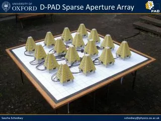
Mid-Frequency Aperture Array ~60m Tile Support Bunker • Freq range 0.3 1.2 GHz • Dense array (Nyquist sampled) • ~75,000 Receiver chains Station Processing – Cape Town
EMBRACE - SKADS Station Processor
The AA Station Next Proc. Bunker n x Optical fibres per 2nd stage processor >1016 MACs Station Processor 1 } 1st Stage Processors Mid P1 Station Processor 2 Mid P2 AA-hi To Correlator . … Mid Py 0.3-1.0GHz Analog links Internal Digital links Station Processor X . . Box O-E? Low P1 Phase Standard & Distribution .. Phase transfer over fibre ... . . O-E? Low Pz Control processors 500MHz Analog links To Central Control AA-lo 10Gb Digital fibre links Prev. Proc. Bunker Station Processing – Cape Town
1-D Beamforming Incoming signal Geometric Delay, t Elements Electronic Delay Beam + + + + + + + + + + + + + + + + + + + + + + + + t Delay 0 Element # Station Processing – Cape Town
1-D Beamforming Incoming signal Geometric Delay, t Elements Spectral Separation + Electronic Delay Beam + + + + + + + + + + + + + + + + + + + + + + + + C0I0+ C1I1+ C2I2+ C3I3+ C4I4+ C5I5 + C6I6+ C7I7+ C8I8+ C9I9+ C10I10+ C11I11+ C12I12+ C13I13+ C14I14+ C15I15 + C16I16+ C17I17+ C18I18+ C19I19+ C20I20+ C21I21+ C22I22+ C23I23 Using Phase delay approximation in narrow frequency bands C0I0+ C1I1+ C2I2+ C3I3+ C4I4+ C5I5+...... Station Processing – Cape Town
Hierarchical structure Incoming signal Geometric Delay, t Elements Electronic Delay + + + + + + + + + + + + + + + + + + + + + + + Tiles Station processor Beam + + + + + Station Processing – Cape Town
Ae AA Station Implementation Tile beam data Station Processor TH_n ….. ….. TH_1 Ae Tile Processor - hi TH_0 ….. ……. To Correlator ….. Ae Station beam data Station Processing – Cape Town
Survey Speed – AA’s forte! At 1 GHz with 250 deg2 FoV: • AA station is big: say 60m dia. small beams ~0.28º width • So, many, many station beams: >3000 ! • But, Tile beams are larger, ~5º width • So, # of Tile beams required: 10 Easy....? Station Processor
Visually.. Station beams Tile beam Great! Constrains data rate of Tile Station processor Station Processing – Cape Town
Ah, but... Station beams Tile beam Only perfect for the centralbeam on Tile beam This is what we’ve done..... Station Processing – Cape Town
Tile Beamforming Incoming signal Elements Electronic Delay + + + + + + + + + + + + + + + + + + + + + + + Tiles Station processor Beam + + + + + t Delay Discontinuities will give high sidelobes and variable forward gain: Dynamic range badly affected Tile Beam 0 Element # Station Processing – Cape Town
Some Consequences • Need ‘extra’ Tile beams over minimum calculated. • Probably also interpolate between Tile beams for more precision • Performance can still be arbitrarily good: dynamic range etc. Maybe on limited FoV. • Bandwidth from Tiles to Station processor determined on quality of beams as well as FoV: still programmable. • Concentrate beamforming centrally as much as possible • Calculating “allowable error”, hence Tile Station Proc. Communications requirment is “work-in-progress” Hierarchical Beamforming looks best option Station Processing – Cape Town
AA Station Processor Reqts. • Beamform the output of all the Tile processors into Station beams • Send “correlator ready” data over fibre to the central processor • Part of the station calibration scheme • Flexibly handle the data from the AA-hi and AA-lo arrays • Maybe provide the ‘F’ part of the FX correlator • Maybe provide station data for local processing • Possibly hold ‘observation history’ data to post process • Be readily scaleable for: • Number of tiles c. Internal station data rates • Data bandwidth to correlator d. Data length to correlator Station Processor
Outline spec. of Processing Chip Inputs Outputs Processing Device: PChip 1013 MAC or 10 TMAC 0 0 1 1 Each Stream: 12 x 10Gb/s 2 2 3 3 4 4 5 5 Station Processing – Cape Town
PChipB’forming requirements • Assuming: All 6 outputs at full speed using all 6 inputs 2 reals per complex sample and 4 real MACs per complex MAC. • 6 inputs, I0 – I5 and 6 outputs O0 – O5. • Beamforming for one output stream: • On = C0I0+ C1I1+ C2I2+ C3I3+ C4I4+ C5I5 • The input data rate per stream is 120Gb/s raw: 96Gb/s actual • Each complex sample is 2 x 4 bit reals so: ~12.5GS/s per stream. • Processing per output stream is: 4*6*12.5 = 300 GMACs • Total processing for 6 output streams = 1,800 GMACs. • This is well within the PChip capability of 10TMACs • Maybe some pre-processing required on each sample. Station Processing – Cape Town
Station Comms • 120 Gb/s total • 50m range • Power: • Tx: 2.4 watts • Rx: 2.0 watts • 12-channel fibre • 10Gb/s channels • VCSEL technology • Pluggable • 19mm pitch Station Processor
Ae AA Station Data rates TH_n ….. ….. 12 fibre lanes @10Gb/s each 12 fibre lanes @10Gb/s each Long distance drivers e/o TH_1 e/o Ae e/o Tile Processor - hi o/e e/o TH_0 Station Processor 0 o/e ….. o/e o/e ….. e/o o/e e/o o/e e/o ….. ……. e/o e/o Ae e/o Long distance drivers e/o o/e e/o o/e o/e o/e ….. 1.0-1.2GHz analogue ….. o/e Inputs #: 1296 Channel rate: 120Gb/s (raw) Total i/p rate: 1.5 Pb/s Typical: AA-hi tiles: 300 AA-lo tiles: 45 Total: 345 I/p data rate: 42Tb/s o/e ………... o/e ….. o/e To Correlator ……. ….. Tile Processor - lo e/o 10Gb/s fibre e/o ….. e/o .... ….. ….. e/o Max 4 Station Processors Station Processor n Long distance drivers TL_0 TL_1 1.0 GHz analogue ….. ….. Notes: 1. No control network shown 2. Up to 4 station processor systems can be implemented in parallel 3. Data shown are raw, typ. get 80% data Local Processing e.g. Cal; pulsars TL_m Station Processing – Cape Town
Each link is 12 diff. copper lanes@10Gb/s 0 o/e PChip PChip e/o 1 o/e e/o 2 o/e e/o 3 o/e e/o 4 o/e e/o 5 o/e e/o o/e PChip PChip e/o o/e e/o o/e e/o o/e e/o o/e e/o o/e e/o 12-channel Rx module. e.g Avago AFBR-820BXXZ 12-channel Tx module. e.g Avago AFBR-810BXXZ o/e PChip PChip e/o o/e e/o o/e e/o o/e e/o To 1st stage Processors or Primary Station Processors To Secondary Station Processors or long distance fibre drivers o/e e/o o/e e/o o/e PChip PChip e/o o/e e/o o/e e/o o/e e/o o/e e/o o/e e/o Each link is 12 fibre lanes@10Gb/s Each link is 12 fibre lanes@10Gb/s o/e PChip PChip e/o o/e e/o o/e e/o o/e e/o o/e e/o o/e e/o 30 o/e PChip PChip e/o 31 o/e e/o Total Raw input data rate: 4.32Tb/s “All to All” Connections Total Raw output data rate: 4.32Tb/s max 32 o/e e/o 33 o/e e/o 34 o/e e/o 35 o/e e/o Control Processor Line Tx/Rx Station Control Station Processor Board Station Processor Station Processor August 2009
Primary Station Processor Board 1 Primary Station Processor Board (max 35) ….. ….. Station Processor system (120Gb/s per Tile) Station Processor Primary Station Processor Board 0 Secondary Station Processor Board 0 Long distance drivers 0 Max no. of Tiles AA-hi+AA-lo is 1296 1 0 2 1 2 ….. ….. ….. ….. ….. 35 AA-hi Secondary Station Processor Board 1 Long distance drivers ….. ….. ….. To each 1st stage Processor ….. To Correlator ….. ….. Secondary Station Processor Board (max 35) Long distance drivers AA-lo “All to All” Connections ….. ….. ….. ….. Each correlator channel is10Gb/s (maybe colour multiplexed together) Each link is 12 fibre lanes@10Gb/s Each link is 12 fibre lanes@10Gb/s Station Processing – Cape Town
Long distance drives PChip e/o e/o e/o e/o e/o Block 0 e/o e/o e/o e/o e/o e/o 12-channel Rx module. e.g Avago AFBR-820BXXZ e/o Each link is fibre10Gb/s raw 0 o/e To Secondary Station Processors To Correlator ….. 1 o/e 2 o/e 3 o/e 4 o/e Long distance 10km Tx module. 5 o/e e/o e/o Each link is 12 fibre lanes@10Gb/s e/o e/o e/o Block 5 e/o e/o Total Raw output data rate: 720Gb/s max e/o e/o Total Raw input data rate: 720Gb/s e/o e/o e/o Control Processor Line Tx/Rx Station Control Station Processor
Estimated Costs (120Gb/s per Tile) Total: €480k Station Processor
Conclusions • Beamform to 1 chip depth at the Tile • Station Processor data rate is much higher than output • Processing performance is unlikely to be an issue • Comms costs and performance critical • Focus on making wide-area comms cheaper! AA Station Beamforming can be done! Station Processor