Download
1 / 35
350 likes | 470 Views
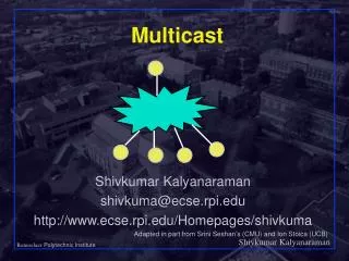
ECSE-4670: Computer Communication Networks (CCN). Network Layer Shivkumar Kalyanaraman: shivkuma@ecse.rpi.edu Biplab Sikdar: sikdab@rpi.edu http://www.ecse.rpi.edu/Homepages/shivkuma. understand principles behind network layer services: Internetworking concepts The network layer IP

E N D
ECSE-4670: Computer Communication Networks (CCN) Network Layer Shivkumar Kalyanaraman: shivkuma@ecse.rpi.edu Biplab Sikdar: sikdab@rpi.edu http://www.ecse.rpi.edu/Homepages/shivkuma
understand principles behind network layer services: Internetworking concepts The network layer IP routing (path selection) how a router works ChapterGoals
Internetworking network layer services IP routing principle: path selection hierarchical routing Internet routing protocols reliable transfer intra-domain inter-domain what’s inside a router? Overview
The Internetworking Problem • Two nodes communicating across a “network of networks”… • How to transportpackets through this heterogeneous mass ? A B
The Internetworking Problem • Problems: heterogeneity and scaling • Heterogeneity: • How to interconnect a large number of disparate networks ? (lower layers) • How to support a wide variety of applications ? (upper layers) • Scaling: • How to support a large number of end-nodes and applications in this interconnected network ?
Heterogeneity: Solutions • Translation (eg: bridges): specify a separate mapping between every pair of protocols (+) No software changes in networks required. () Need to specify N mappings when a new lower layer protocol is added to the list () When many networks, subset = 0 () Mapping may be asymmetric
Heterogeneity: Solutions • Overlay model: Define a new protocol (IP) and map all networks to IP (+) Require only one mapping (IP -> new protocol) when a new protocol is added (+) Global address space can be created for universal addressibility and scaling ()Requires changes in lower networks (eg: protocol type field for IP)
Heterogeneity: Solutions () IP has to be necessarily simple else mapping will be hard. • Even in its current form mapping IP to ATM has proven to be really hard. • Basis for “best-effort” forwarding ()Protocol mapping infrastructure needed: address hierarchy, address resolution, fragmentation
Host, router network layer functions: • ICMP protocol • error reporting • router “signaling” • IP protocol • addressing conventions • datagram format • packet handling conventions • Routing protocols • path selection • RIP, OSPF, BGP routing table The Internet Network layer Transport layer: TCP, UDP Network layer Link layer physical layer
IP address: 32-bit identifier for host, router interface interface: connection between host, router and physical link router’s typically have multiple interfaces host may have multiple interfaces IP addresses associated with interface, not host, router 223.1.1.2 223.1.2.1 223.1.3.27 223.1.3.1 223.1.3.2 223.1.2.2 IP Addressing: introduction 223.1.1.1 223.1.2.9 223.1.1.4 223.1.1.3 223.1.1.1 = 11011111 00000001 00000001 00000001 223 1 1 1
IP address: network part (high order bits) host part (low order bits) What’s a network ? (from IP address perspective) device interfaces with same network part of IP address can physically reach each other without intervening router IP Addressing - 1 223.1.1.1 223.1.2.1 223.1.1.2 223.1.2.9 223.1.1.4 223.1.2.2 223.1.3.27 223.1.1.3 LAN 223.1.3.2 223.1.3.1 network consisting of 3 IP networks (for IP addresses starting with 223, first 24 bits are network address)
How to find the networks? Detach each interface from router, host create “islands of isolated networks 223.1.3.27 223.1.3.1 223.1.3.2 IP Addressing - 2 223.1.1.2 223.1.1.1 223.1.1.4 223.1.1.3 223.1.7.0 223.1.9.2 223.1.9.1 223.1.7.1 223.1.8.1 223.1.8.0 223.1.2.6 223.1.2.1 223.1.2.2 Interconnected system consisting of six networks
multicast address 1110 network host 110 network 10 host IP Addresses given notion of “network”, let’s re-examine IP addresses: “class-full” addressing: class 1.0.0.0 to 127.255.255.255 A network 0 host 128.0.0.0 to 191.255.255.255 B 192.0.0.0 to 223.255.255.255 C 224.0.0.0 to 239.255.255.255 D 32 bits
Some Special IP Addresses • All-0s This computer • All-1s All hosts on this net (limited broadcast: don’t forward out of this net) • All-0 host suffix Network Address (‘0’ means ‘this’) • All-1 host suffix All hosts on the destination net (directed broadcast). • 127.*.*.* Loopback through IP layer
IP addressing: CIDR - 1 • classful addressing: • inefficient use of address space, address space exhaustion • e.g., class B net allocated enough addresses for 65K hosts, even if only 2K hosts in that network
host part network part 11001000 0001011100010000 00000000 200.23.16.0/23 IP addressing: CIDR - 2 • CIDR: Classless InterDomain Routing • network portion of address of arbitrary length • address format: a.b.c.d/x, where x is # bits in network portion of address
Subnet Addressing • External routers need to store entries only for the “network ID” • Internal routers & hosts use subnetmask to identify “subnet ID” and route packets between “subnets” within the “network”. • Eg: Mask: 255.255.255.0 => subnet ID = 8 bits with upto 62 hosts/subnet
Subnet Addressing (Continued) • Route table lookup: • IF ((Mask[i] & Destination Addr) = = Destination[i]) Forward to NextHop[i] • Subnet mask can end on any bit. • Mask must have contiguous 1s followed by contiguous zeros. Routers do not support other types of masks.
Destination Mask Next Hop 30.0.0.0 255.0.0.0 40.0.0.7 40.0.0.0 255.0.0.0 Deliver direct 128.1.0.0 255.255.0.0 Deliver direct 192.4.10.0 255.255.255.0 128.1.0.9 Route Table Lookup: Example 30.0.0.7 40.0.0.8 128.1.0.9 40.0.0.0 30.0.0.0 128.1.0.0 192.4.0.0 40.0.0.7 128.1.0.8 192.4.10.9
IP addresses: how to get one? Hosts (host portion): • hard-coded by system admin in a file • DHCP: Dynamic Host Configuration Protocol: dynamically get address: “plug-and-play” • host broadcasts “DHCP discover” msg • DHCP server responds with “DHCP offer” msg • host requests IP address: “DHCP request” msg • DHCP server sends address: “DHCP ack” msg
IP addresses: how to get one? Network (network portion): • get allocated portion of ISP’s address space: ISP's block 11001000 00010111 00010000 00000000 200.23.16.0/20 Organization 0 11001000 00010111 00010000 00000000 200.23.16.0/23 Organization 1 11001000 00010111 00010010 00000000 200.23.18.0/23 Organization 2 11001000 00010111 00010100 00000000 200.23.20.0/23 ... ….. …. …. Organization 7 11001000 00010111 00011110 00000000 200.23.30.0/23
200.23.16.0/23 200.23.18.0/23 200.23.30.0/23 200.23.20.0/23 . . . . . . Hierarchical addressing: route aggregation Hierarchical addressing allows efficient advertisement of routing information: Organization 0 Organization 1 “Send me anything with addresses beginning 200.23.16.0/20” Organization 2 Fly-By-Night-ISP Internet Organization 7 “Send me anything with addresses beginning 199.31.0.0/16” ISPs-R-Us
200.23.16.0/23 200.23.18.0/23 200.23.30.0/23 200.23.20.0/23 . . . . . . Hierarchical addressing:more specific routes ISPs-R-Us has a more specific route to Organization 1 Organization 0 “Send me anything with addresses beginning 200.23.16.0/20” Organization 2 Fly-By-Night-ISP Internet Organization 7 “Send me anything with addresses beginning 199.31.0.0/16 or 200.23.18.0/23” ISPs-R-Us Organization 1
IP addressing: the last word... Q:How does an ISP get block of addresses? A:ICANN: Internet Corporation for Assigned Names and Numbers • allocates addresses • manages DNS • assigns domain names, resolves disputes
IP datagram: 223.1.1.1 223.1.2.1 E B A 223.1.1.2 source IP addr 223.1.2.9 misc fields dest IP addr 223.1.1.4 data 223.1.2.2 223.1.3.27 223.1.1.3 223.1.3.2 223.1.3.1 Dest. Net. next router Nhops 223.1.1 1 223.1.2 223.1.1.4 2 223.1.3 223.1.1.4 2 Getting a datagramfrom source to dest. - 1 routing table in A datagram remains unchanged, as it travels source to destination addr fields of interest here
223.1.1.1 223.1.2.1 A E B 223.1.1.2 223.1.2.9 223.1.1.4 223.1.2.2 223.1.3.27 223.1.1.3 223.1.3.2 223.1.3.1 Dest. Net. next router Nhops 223.1.1 1 223.1.2 223.1.1.4 2 223.1.3 223.1.1.4 2 Getting a datagramfrom source to dest. - 2 misc fields data 223.1.1.1 223.1.1.3 • Starting at A, given IP datagram addressed to B: • look up net. address of B • find B is on same net. as A • link layer will send datagram directly to B inside link-layer frame • B and A are directly connected
223.1.1.1 223.1.2.1 A E B 223.1.1.2 223.1.2.9 223.1.1.4 223.1.2.2 223.1.3.27 223.1.1.3 223.1.3.2 223.1.3.1 Dest. Net. next router Nhops 223.1.1 1 223.1.2 223.1.1.4 2 223.1.3 223.1.1.4 2 Getting a datagramfrom source to dest. - 3 misc fields data 223.1.1.1 223.1.2.2 • Starting at A, dest. E: • look up network address of E • E on different network • A, E not directly attached • routing table: next hop router to E is 223.1.1.4 • link layer sends datagram to router 223.1.1.4 inside link-layer frame • datagram arrives at 223.1.1.4 • continued…..
Dest. next 223.1.1.1 network router Nhops interface 223.1.2.1 E B A 223.1.1 - 1 223.1.1.4 223.1.1.2 223.1.2 - 1 223.1.2.9 223.1.2.9 223.1.1.4 223.1.3 - 1 223.1.3.27 223.1.2.2 223.1.3.27 223.1.1.3 223.1.3.2 223.1.3.1 Getting a datagramfrom source to dest. – 4 misc fields data 223.1.1.1 223.1.2.2 • Arriving at 223.1.4, destined for 223.1.2.2 • look up network address of E • E on same network as router’s interface 223.1.2.9 • router, E directly attached • link layer sends datagram to 223.1.2.2 inside link-layer frame via interface 223.1.2.9 • datagram arrives at 223.1.2.2!!! (hooray!)
IP Features • Connectionless service • Addressing • Data forwarding • Fragmentation and reassembly • Supports variable size datagrams • Best-effort delivery • Provides only “Send” and “Delivery” services. Error and control messages generated by Internet Control Message Protocol (ICMP)
What IP does NOT provide • End-to-end data reliability & flow control (done by TCP or application layer protocols) • Sequencing of packets (like TCP) • Error detection in payload (TCP, UDP or other transport layers) • Error reporting (ICMP)
What IP does NOT provide (Continued) • Setting up route tables (RIP, OSPF, BGP etc) • Connection setup (it is connectionless) • Address/Name resolution (ARP, RARP, DNS) • Configuration (BOOTP, DHCP) • Multicast (IGMP, MBONE)
IP datagram format IP protocol version number 32 bits total datagram length (bytes) header length (bytes) type of service head. len ver length for fragmentation/ reassembly fragment offset “type” of data flgs 16-bit identifier max number remaining hops (decremented at each router) upper layer time to live Internet checksum 32 bit source IP address 32 bit destination IP address upper layer protocol to deliver payload to E.g. timestamp, record route taken, pecify list of routers to visit. Options (if any) data (variable length, typically a TCP or UDP segment)
network links have MTU (max.transfer size) - largest possible link-level frame. different link types, different MTUs large IP datagram divided (“fragmented”) within net one datagram becomes several datagrams “reassembled” only at final destination IP header bits used to identify, order related fragments IP Fragmentation & Reassembly - 1 fragmentation: in: one large datagram out: 3 smaller datagrams reassembly
length =1500 length =4000 length =1040 length =1500 ID =x ID =x ID =x ID =x fragflag =0 fragflag =1 fragflag =0 fragflag =1 offset =1480 offset =2960 offset =0 offset =0 IP Fragmentation and Reassembly - 2 One large datagram becomes several smaller datagrams
Summary • Internet architectural principles • IP addressing and header • Fragmentation/Reassembly, Path MTU discovery