Download
1 / 46
460 likes | 617 Views
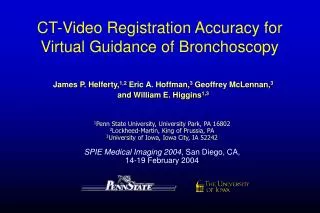
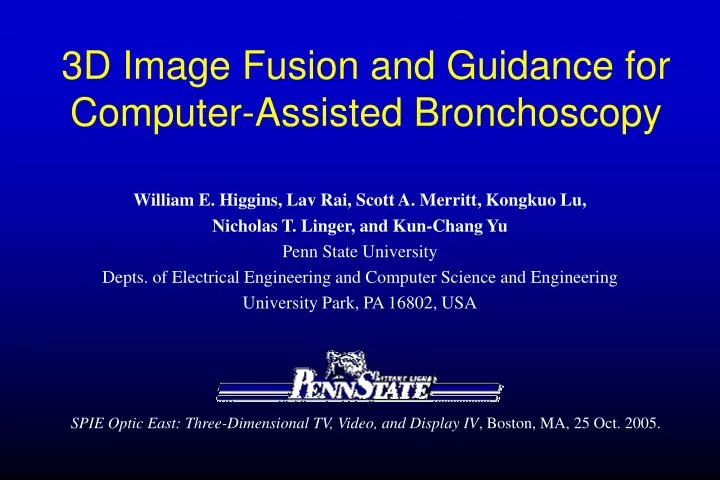
3D Image Fusion and Guidance for Computer-Assisted Bronchoscopy. William E. Higgins, Lav Rai, Scott A. Merritt, Kongkuo Lu, Nicholas T. Linger, and Kun-Chang Yu Penn State University Depts. of Electrical Engineering and Computer Science and Engineering University Park, PA 16802, USA.

E N D
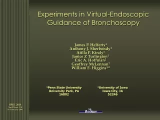
3D Image Fusion and Guidance for Computer-Assisted Bronchoscopy William E. Higgins, Lav Rai, Scott A. Merritt, Kongkuo Lu, Nicholas T. Linger, and Kun-Chang Yu Penn State University Depts. of Electrical Engineering and Computer Science and Engineering University Park, PA 16802, USA SPIE Optic East: Three-Dimensional TV, Video, and Display IV, Boston, MA, 25 Oct. 2005.
Lung Cancer • Lung Cancer: #1 cancer killer, 30% of all cancer deaths, 1.5 million deaths world-wide, < 15% 5-year survival rate (nearly the worst of cancer types) • To diagnose and treat lung cancer, • 3D CT-image preplanning – noninvasive • Bronchoscopy – invasive • 500,000 bronchoscopies done each year in U.S. alone Procedure is LITTLE HELP if diagnosis/treatment are poor • A test for CT Image-based Lung-Cancer Screening in progress! 10-30 million patient population in U.S. alone! Screening is WORTHLESS if diagnosis/treatment are poor
3D CT Chest Images Typical chest scan V(x,y,z): • 500 512X512 slices V(x,y,.) • 0.5mm sampling interval
3D Mental Reconstruction How physicians assess CT scans now
volume/surface rendering4 multi-planar reconstruction2 projection imaging1 virtual endoscopic rendering5 STS-MIP sliding-thin-slab maximum intensity projection6 curved-section reformatting3 Visualization Techniques – see “inside” 3D Images 1{Hohne87,Napel92} 2{Robb1988,Remy96,McGuinness97} 3{Robb1988,Hara96,Ramaswamy99} 4{Ney90,Drebin88,Tiede90} 5{Vining94,Ramaswamy99, Helferty01} 6{Napel, 92}
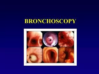
For “live” procedures Bronchoscopy video from bronchoscope IV(x,y) Figure 19.4, Wang/Mehta ‘95
Difficulties with Bronchoscopy • Physician skill varies greatly! • Low biopsy yield. Many “missed” cancers. • Biopsy sites are beyond airway walls – biopsies are done blindly!
Input a high-resolution 3D CT chest image • virtual copy of chest anatomy • Use computer to explore virtual anatomy • permits unlimited “exploration” • no risk to patient Virtual Endoscopy (Bronchoscopy) Endoluminal Rendering ICT(x,y) (inside airways)
Image-Guided Bronchoscopy Systems Show potential, but recently proposed systems have limitations: • CT-Image-based • McAdams et al.(AJR 1998) and Hopper et al.(Radiology 2001) • Bricault et al. (IEEE-TMI 1998) • Mori et al. (SPIE Med. Imaging 2001, 2002) • Electromagnetic Device attached to scope • Schwarz et al.(Respiration 2003) Our system: reduce skill variation, easy to use, reduce “blindness”
Our System: Hardware Video AGP card Matrox PCI card PC Enclosure AVI File Video Stream Matrox Cable Video Capture Main Thread Video Tracking OpenGL Rendering Worker Thread Mutual Information Dual CPU System Scope Monitor RGB, Sync, Video Scope Processor Rendered Image Light Source Endoscope Polygons, Viewpoint Image Computerdisplay Software written in Visual C++.
3D CT Scan Bronchoscope Stage 1: 3D CT Assessment • Segment 3D Airway Tree • Calculate Centerline Paths • Define Target ROI biopsy sites • Compute polygon data Stage 2: Live Bronchoscopy For each ROI: • Present virtual ROI site to physician • Physician moves scope “close” to site • Do CT-Video registration and fusion • Repeat steps (1-3) until ROI reached Case Study Our System: Work Flow Data Sources Data Processing
Stage 1: 3D CT Assessment (Briefly) • Segment Airway tree (Kiraly et al., Acad. Rad. 10/02) 2. Extract centerlines (Kiraly et al., IEEE-TMI 11/04) 3. Define ROIs (e.g., suspect cancer) 4. Compute tree-surface polygon data (Marching Cubes – vtk) CASE STUDY to help guide bronchoscopy
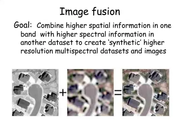
Register Virtual 3D CT World ICT(x,y) (Image Source 1) To the Real Endoscopic Video World IV(x,y) (Image Source 2) • Maximize normalized mutual information to get Stage 2: Bronchoscopy - Key Step:CT-VideoRegistration
CT-Video Registration: 1) Match viewpoints of two cameras Both image sources, IV and ICT , are cameras. 6-parameter vector representing camera viewpoint 3D point mapped to camera point (Xc , Yc) through the standard transformation The final camera screen point is given by (x, y) where
Bronchoscope Video Camera Model Following Okatani and Deguchi (CVIU 5/97), assume video frame I(p) abides by a Lambertian surface model; i.e., where qs = light source-to-surface angle R = distance from camera to surface point p
Make FOVs of both Cameras equal To facilitate registration, make both cameras IV and ICT have the same FOV. To do this, use an endoscope calibration technique (Helferty et al., IEEE-TMI 7/01). Measure the bronchoscope’s focal length (done off-line): Then, the angle subtended by the scope’s FOV is Use same value for endoluminal renderings, ICT.
Bronchoscope Calibration Device Capture known dot pattern. Compute Calibration parameters from frame. Captured Frame See Helferty et al., IEEE Trans. Med. Imaging, July 2001.
CT (Endoluminal Rendering) Camera Model Related to video frame model I(p): where qs = light source-to-surface angle qp= angle between camera axis and vector pointing toward p R = distance from camera to surface point p (from range map) La = ambient light (indirect lighting) Use OpenGL
Normalized Mutual Information Mutual Information (MI) – used for registering two different image sources: a) Grimson et al. (IEEE-TMI 4/96) b) Studholme et al. (Patt. Recog. 1/99) normalized MI (NMI)
Normalized Mutual Information Normalized mutual information (NMI): where and is a histogram (marginal density) “optimal” pV,CT
CT-Video Registration – Optimization Problem Given a fixed video frame and starting CT view Search for the optimal CT rendering subject to where viewpoint is varied over Optimization algorithms used: step-wise, simplex, and simulated annealing
Simplex Optimization A simplex is an N dimensional figure with N+1 vertices Reflection Expansion Collapse Collapse Simplex
CT-Video Optimization Example initial p V,CT Fixed Video Frame Optimal CT Rendering optimal p V,CT
System Results Three sets of results are presented: • Phantom Test controlled test, free of subject motion • Animal Studies controlled in vivo (live) tests • Human Lung-Cancer Patients real clinical circumstances
A. Phantom Test Goal: Compare biopsy accuracy under controlled stationary circumstancesusing (1) the standard CT-film approach versus (2) image-guided bronchoscopy. Experimental Set-up: Rubber phantom - human airway tree model used for training new physicians. CT Film - standard form of CT data.
Phantom Accuracy Results (6 physicians tested) Film biopsy accuracy:5.53mm Std Dev:4.36mm Guided biopsy accuracy:1.58mm Std Dev:1.57mm Physician film accuracy (mm) guided accuracy (mm) 1 5.80 1.38 2 2.73 1.33 3 4.00 1.49 4 8.87 1.60 5 8.62 2.45 6 3.19 1.24 • ALL physicians improved greatly with guidance • ALL performed nearly the SAME with guidance!
biopsy dart Computer system during animal test (done in EBCT scanner suite). B. Animal Studies Goals: Test the performance of the image-guided system under controlled in vivo circumstances (breathing and heart motion present). Experimental Set-up:
Composite View after All Real Biopsies Performed Rendered view of preplanned biopsy Sites Thin-slab DWmax depth-view of 3D CT data AFTER all darts deposited at predefined sites. Bright “flashes” are the darts.
Registered Virtual ROI on Video Virtual-World CT rendering ICT Real-World targetvideo IV Stage 2: Image-Guided Bronchoscopy (case h005 [UF], mediastinal lymph-node biopsy, in-plane res. = 0.59mm, slice spacing = 0.60mm)
Case DC: performing a biopsy Left view: Real-time bronchoscopic video view; biopsy needle in view Center: Matching virtual-bronchoscopic view showing preplanned region (green) Right: Preplanned region mapped onto bronchoscopic view, with biopsy needle in view. Distance to ROI = scope’s current distance from preplanned biopsy site (ROI). • All nodal-region samples showed normal appearing lymphocytes. • Subsequent open-lung biopsy showed a suspect mass to be inflammatory tissue. 40 lung-cancer patients done to date
Comments on System Effective, easy to use A technician – instead of $$ physician – performs nearly all operations Gives a considerable “augmented reality” view of patient anatomy less physician stress Fits seamlessly into the clinical lung-cancer management process. Appears to greatly reduce the variation in physician skill level. This work was partially supported by: NIH Grants #CA74325, CA91534, HL64368, and RR11800 Whitaker Foundation, Olympus Corporation
Lung Cancer • Lung Cancer: #1 cancer killer, 30% of all cancer deaths, 1.5 million deaths world-wide, < 15% 5-year survival rate (nearly the worst of cancer types) • To diagnose and treat lung cancer, • 3D CT-image assessment – preplanning, noninvasive • Bronchoscopy – invasive Procedure is LITTLE HELP if diagnosis/treatment are poor
Normalized Mutual Information Mutual Information (MI) – used for registering two different image sources: a) Grimson et al. (IEEE-TMI 4/96) b) Studholme et al. (Patt. Recog. 1/99) normalized MI (NMI) We use normalized mutual information (NMI) for registration: