Download
1 / 42
800 likes | 1.74k Views
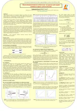
Electrode Material for the Electrochemical Oxidation of Organic Pollutants for Wastewater Treatment. Christos Comninellis Swiss Federal Institute of Technology GGEC-ISIC-SB-EPFL 1015- Lausanne, Switzerland.

E N D
Electrode Material for the Electrochemical Oxidation of Organic Pollutants for Wastewater Treatment Christos Comninellis Swiss Federal Institute of Technology GGEC-ISIC-SB-EPFL 1015- Lausanne, Switzerland
Laboratory scale equipment used for electrochemical oxidation of organics for wastewater treatment One compartment cell in batch operation
Bench scale equipment used for electrochemical oxidation of organics for wastewater treatment One compartment cell in continuous or batch operation
Pilot-plant equipment used for electrochemical oxidation of organics for wastewater treatment One compartment cell in continuous or batch operation
Involved reactions in the electrochemical treatment Anode Cathode Oxidation: R + H2O RO + 2H+ + 2e- (main reaction) H2O 1/2O2 + 2H+ + 2e- (side reaction) Reduction: 2H+ + 2e- H2 (wastewater) Global reaction: R + H2O RO + H2 (main reaction) H2O 1/2O2 + H2 (side reaction)
ICE (-) I (A) V(volt) Vav ACE t (s) t (s) t (s) t Definition of global parameters Operation at constant current t t • Instantaneous rate of COD elimination (mol O2/s) : • Average rate of COD elimination (mol O2/s) : • Electrochemical oxygen demand (mol O2/l) : • Electrochemical COD conversion (%) :
Proposed model for the anodic oxidation of organics in acid media • Water discharge to hydroxyl radicals ii) Oxidation of organics R with electro-generated OH radicals (main reaction) iii) Oxygen evolution (side reaction) : represents an active site on the anode surface
(side reaction) Definition of instantaneous current efficiency (ICE) and average current efficiency (ACE) in the electrochemical treatment process (main reaction) Instantaneous current efficiency Average current efficiency t : electrolysis time
(main reaction) (side reaction) Measurement of the instantaneous current efficiency (ICE) Two main techniques have been used for ICE measurements: I) COD method F: 96485 C mol-1 V: electrolyte volume (m3) I : applied current (A) COD: Chemical oxygen demand (mol O2m-3) Dt: time interval II) O2flow rate method : Calculated O2 flow rate from Faradays low (m3 O2/s) : measured O2 flow rate during electrolysis (m3 O2/s)
(main reaction) (side reaction) Influence of anode material on ICE • Relation between M-OH adsorption enthalpy and • Chemical reactivity of OH radical (main reaction) • Electrochemical reactivity of OH radical (side reaction) • Low M-OH adsorption enthalpy (physisorption of OH radical on M) results • in an increase of the chemical reactivity of OH radicals « high Oxidation • power anodes » (favor main reaction) • High M-OH adsorption enthalpy (chemisorption of OH radical on M) results • in an increase of the electrochemical reactivity of OH radicals « low Oxidation • power anodes »(favor side reaction)
+ - + ® + + IrO H O IrO ( OH ) H e 2 2 2 1 + - ® + + ® + IrO ( OH ) IrO H e IrO IrO O 2 3 3 2 2 2 Investigation of the oxygen evolution reaction (side reaction) IrO2: « low Oxidation power anode » (electrocatalytic) BDD : «high Oxidation power anode » (non-electrocatalytic) + - + ® + + BDD H O BDD ( OH ) H e 2 1 + - + + + + ® BDD ( OH ) BDD O H e 2 2
DE 5000 DE IrO2 4000 3000 2000 BDD 1000 0 0 4 8 12 -1 specific charge [Ah L ] Investigation of the oxidation reaction (main reaction)Oxalic acide oxidation on BDD and IrO2 BDD « high Oxidation power anode » IrO2 « low Oxidation power anode » oxalic acid conc. [mol L-1]
X X log ACE x NH2 x OH x COOH x SO3H x NO2 s log ACE OH x SO3H x x NH2 x COOH s Influence of anode material on the ACE Oxidation of benzene derivatives under conditions were there is no mass transport limitation. • i)«low oxidation power anodes» (Pt) • ACE decrease with increasing the Hamet constant s of X substituent. • log ACE = -2s - 1.3 • This indicates that the reaction is electrophilic in nature* *GWA 11,792-797 (1992) ii) «high oxidation power anodes»(BDD) ACE is practically independent of the Hamet constant s of X substituent. ACE = 1
Detection of HO. radicals formed by water discharge on BDD anode H2O HO.+ H+ + e- Fenton BDD : 2h BDD : 1h Electron spin resonance (ESR) spectra in the presence of 5,5-dimethyl –1-pyrroline-1-oxide (DMPO) spin-trap DMPO 10-3 g.l-1, i = 10-4 A.cm-2.
Detection of HO. radicals formed by water discharge on BDD anode H2O HO. + H+ + e-
Anodic production of H2O2 on BDD Anodic production of H2O2 on BDD at different current densities: ()230 A cm-2, ()470 A cm-2, ()950 A cm-2 and (x)1600 A cm-2 during electrolysis of 1M HClO4on BDD electrode T=25°C.
HCOOH (COOH)2 HClO4 Oxalic acid Formic acid Cformic = Coxalic = 0.5 M Electrolyte HClO4 1M j = 238 A m-2 k’OH = 1.4 10 6 L mol-1 s-1 kOH = 1.3 10 8 L mol-1 s-1 Competition Reaction of Hydroxyl Radicals with Carboxylic AcidsÒxidation of Oxalic and Formic Acids
Proposed model for the anodic oxidation of organics in acid media (a) water discharge to hydroxyl radicals, (b) oxygen evolution by electrochemical oxidation of hydroxyl radicals, (c) formation of the higher metal oxide at “low oxydation power anodes”, (d) oxygen evolution by chemical decomposition of the higher metal oxide (e) oxidation of the organic compound, R, via hydroxyl radicals at “high oxydation power anodes”, ; (f) oxidation of the organic compound via the higher metal oxide at “low oxydation power anodes”,.
Modeling of organics oxidation on«high oxidation power anodes» (BDD)Batch reactorOperation at constant current Estimation of the instantaneous current efficiency ICE a) iappl. < ilim ICE = 100% b) iappl. > ilim ICE < 100%
COD(t) COD0 t or Q dm-3 0.00 ICE (%) 100 t or Q dm-3 0.00
Comparison of model and experimental data values(b-naphthol)
Oxidation of 4-chlorophenol (4-CP) on BDD anode Influence of 4-CP concentration A A : Partial oxidation Conc. A B Conc. B : complete combustion B
Oxidation of 4-chlorophenol (4-CP) on BDD anode Influence of current density A 15 mA/cm2 A : Partial oxidation B B i 60 mA/cm2 A B : complete combustion
Oxidation of organics on BDD electrodes Investigated organic compounds
ICE (-) I (A) V(volt) Vav. ACE t (s) t (s) t (s) t Economical considerations Operation at constant current t t • Specific electrical energy consumption (kWh/kg COD):* • Anodic surface area needed for the elimination of a given amount of COD (kg COD/h) * i = 1 kA/m2 P= 1 kg COD/h ACE= 1 *GWA 11,792-797 (1992)
Modulated current operation I (A) (I) (II) t (h) iappl. = ilim iappl. < ilim iappl. = ilim (II) iappl. > ilim (I) iappl. > ilim
Partial Electrochemical oxidation Biological treatment Combined Electrochemical – Biological treatment non-bio toxic bio non-toxic End of the Electrochemical treatment EC50-10 min (Microtox) End of the Electrochemical treatment 1.0 (Zan-Wellens) 0.5 toxic non-toxic non-bio bio Ah/l Ah/l
Rate of OH production in the RC Rate of R transport in to the RC rR= km [R] (mol m-2 s-1) Partial oxidation or incineration of organics on BDD anode in acid medium Reaction cage (O2,OH,H2O2,Org...) OH R Anode Solution dRC: few Å dRC
Partial oxidation or incineration of phenol • We can define: • the parameter g • the stoichiometry factor n for a given reaction as the number of moles of OH (per mol of R) involved in the reaction.
Partial oxidation of phenol g = 1.3-1.6 (<4) Phenol conversion <20% ICE = 100% Incineration of phenol g 60 (>28) ICE < 100%
P R ze- O Mediated electrochemical treatment A red/ox couple (O/R ), present in the electrolyte, are firstly electro-generated by oxidation at the anode then oxidize the organic pollutant in solution in a homogenous chemical reaction. R (sol) O (sol) + z e-(At the anode) O(sol) + S(sol) R(sol) + P(sol) (In solution ) S Advantage: Avoid problems related with mass transfer limitations
Use both anodic and cathodic reactions* - + 2e- 2 H2O 2e- 2H+ + O2 2 OH* + 2H+ H2O2 Anodic reaction Formation of hydroxyl radicals by water oxidation Cathodic reaction Formation of hydrogen peroxide by oxygen reduction 2H2O 2OH. + 2H+ +2e- O2 + 2H+ + 2e- H2O2 Global reaction : 2H2O + O2 H2O2 + 2 OH. 2F * Ch.Comninellis et al Electrochimica Acta, vol. 49, num. 25 (2004), p. 4487-4496.
Treatment of industrial wastewater Cases studied Laboratory scale (Batch) *New Diamond and Front. Carbon. Technology. Ch.Comninellis et al. 14(4), 239-247 (2004) Pilot plant (1.6 m2) (continuous)
Remaining problems in the electrochemical treatment • Bench scale and pilot plant measurements are needed for each wastewater treatment. • For each wastewater the service life of electrode material should be estimated • High investment cost of the electrochemical unit • Problems inherent to hydrogen production at the cathode • Formation of organochlorinated compounds and Cl2(g) if Cl- are present in the • wastewater • Stripping of VOC with the evolved gas • Deposition of Ca and Mg carbonates at the cathode when working in neutral or • basic media • The composition of the wastewater should be constant (only in plant treatment) • Industrial electrochemistry is not well know in industry
Conclusions • Electrogenerated OH. are the active oxidants involved in the electrochemical oxidation • of organic pollutants. • The main side reaction in the electrochemical oxidation of organic pollutants is oxygen • evolution. • Two techniques have been presented for the determination of the instantaneous current • efficiency (ICE) during the electrochemical oxidation of organic pollutants. • Electrogenerated OH. are chemisorbed on «low oxidation power » anodes (partial • oxidation, low ICE) and physisorbed on « high oxidation power » anodes (complete • oxidation. high ICE) • A model is presented for the oxidation of organics on BDD anode « high oxidation • power » anodes • Working at modulated current density using « high oxidation power » anodes (BDD) can • allow the suppression of the side reaction of oxygen evolution ( ACE=1) • Many technological problems have to solved before the practical application of the technology
Problem 1 2 m3 of a non-biodegradable organic industrial wastewater with a COD of 10 kg/m3 and TOC of 5 kg/m3 is to be pre-treated (before the biological treatment) by anodic oxidation, under galvanostatic conditions (i = 1kA/m2), using a filter press electrochemical reactor with 20 m2 anode surface area. Considering that : After elimination of 60 % of the COD the waste water becomes biodegradable The average current efficiency, for elimination 60% of the initial COD, is 30% The average cell potential during the electrochemical treatment is 4.5 volts Calculate the treatment time and the specific energy consumption (kWh/kg COD eliminated).
Problem 2 A continuous electrochemical plant is to be designed for the treatment of 2 m3/h of an organic industrial wastewater with a COD of 2.5 kg/m3. Considering that : The treatment has been carried out at constant current density (i=1 kA/m2) The average current efficiency for the elimination of 80% of the COD is 35%. The average cell potential during the electrochemical treatment was 5 volts Calculate the required anode surface area and the specific energy consumption (kWh/kg COD eliminated).
Problem 3 3 m3 of a non-biodegradable industrial wastewater with a COD of 12 kg/m3 and TOC of 5 kg/m3 has been pre-treated by anodic oxidation, to transform the non-biodegradable organic compounds to biodegradable. This has been achieved after 5 h of electrolysis under galvanostatic conditions (I=15 kA ) resulting in the elimination of 40% of the initial COD. Calculate the average current efficiency and the amount of O2 formed during the treatment.
Problem 4 • 10 m3 of a non-biodegradable industrial wastewater with a COD of 6 kg/m3 has been pre-treated by anodic oxidation. This treatment has been achieved after 5 h of electrolysis under galvanostatic conditions (I=300 kA) resulting in a TOC of 1kg/m3. • Analysis of the wastewater after the electrochemical treatment shows that the final oxidation product was oxalic acid. • Calculate : • a) The concentration of oxalic acid and the COD after the electrochemical • treatment. • b) The average current efficiency • c) The anode surface area used if the applied current density was 1kA/m2.
Problem 5 A chemical plant produce 5 m3/h of a wastewater with the following composition: Phenol : 3kg/m3 Acetone : 4kg/m3 Na2SO4 : 25 kg/m3 H2SO4 : 5kg/m3 Calculate the anode surface area necessary to eliminate 60% of the COD by anodic oxidation, using a constant current density of 2 kA/m2 and considering an average current efficiency of 50%.
Problem 6 • A chemical plant produce a wastewater with the following composition: • COD : 2.5 kg/m3 • Na2SO4 : 25 kg/m3 • H2SO4 : 5kg/m3 • The treatment has been carried out in an electrochemical reactor characterized • by an average mass transfer coefficient km= 2x10⁻⁵ m/s. • Calculate: • The initial limiting current. • The initial current efficiency if the electrolysis has been carried out at 238 A/m2 • The instantaneous current efficiency (ICE) after elimination 90% of COD using a current density of 238 A/m2 • Propose an operation mode for an optimal operation of the treatment.