Download
1 / 49
490 likes | 697 Views
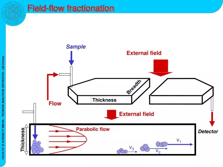
Sample. Breadth. Thickness. Flow. External field. Detector. v 1. Thickness. v 3. v 2. Field-flow fractionation. External field. Parabolic flow. molecul es. particulate. Polymers, Aggregates, Micro-Gels, Particles. Proteins, Viruses, DN A ,. Atom. Molecule. Solids. 1E0. 1E2.

E N D
Sample Breadth Thickness Flow External field Detector v1 Thickness v3 v2 Field-flow fractionation External field Parabolic flow
molecules particulate Polymers, Aggregates, Micro-Gels, Particles Proteins, Viruses, DNA, ... Atom Molecule Solids 1E0 1E2 1E4 1E6 1E8 1E10 1E12 Molar Mass 1 nm 10 nm 100 nm 1 µm Radius FFF working range Micelles, Liposomes, Emulsions Viruses, Bacteria, Cells Proteins, Protein-Complexes, DNA Polymers
Parabolic Flow Profile The transportation stream forms a parabolic flow profile 1. assuming there is no velocity at the accumulation wall x = 0 2. assuming the flow profile is constant along the separation axis 3. modeling the channel as two infinite parallel plates v : is the flow velocity of the carrier liquid <v>: is the average velocity of the carrier liquid x : is the distance to the accumulation wall w : is the channel thickness
Field View from side into channel Flow D Vectors X Accumulation wall U Normal mode: concentration distribution /1 Distribution is a function of „down“ speed U and „up“ speed D c: is the concentration of the solute c0: is the concentration at height zero x: is the distance to the accumulation wall w: is the channel thickness U: is the drift velocity D: is the diffusion coefficient l: is the mean layer thickness λ: is the dimensionless cloud thickness(reduced layer thickness) × x U - ( ) = × c x c e D 0
Normal mode: concentration distribution /2 The mean layer thickness l of the solutes over the accumulation wall is given by the equilibrium between drift velocity U and diffusion coefficient D The drift velocity U is the force F on the solute divided by the friction coefficient f: U = F/f The Nernst-Einstein equation defines the friction coefficient f = kT/D λ: reduced layer thickness w: channel thickness l: mean layer thickness U: drift velocity D: diffusion coefficient T: temperature (°K) k: Boltzmann constant The quantity kT/F is the ratio of thermal energy to the force acting on the analyte particle
1 sample l = 1 sample l = 2 0,5 Conzentration c(x) 0 0 5 10 15 20 distance x Normal mode: concentration distribution /3 Separation takes places if two species have different mean thickness layer lover the accumulation wall, respectively different diffusion coefficients
Normal mode: retention /1 • The retention parameter R is defined as the average velocity V of one species with respect to the average carrier <v> velocity. • The average velocity V is a sum of the product of all different flow rates in the channel flow profile and the corresponding sample concentration c(x) * v(x) divided by the sum of all concentrations c(x) t0: void time tr: retention time c: concentration x: distance to the accumulation wall V0: void volume Vr: retention volume V : average velocity of species <v>: average velocity of carrier
Parabolic flow profile Normal mode: retention /2 Retention parameter R Concentration profile λ : dimensionless cloudthickness (reduced layer thickness) l : mean layer thickness w : channel thickness U : drift velocity D : diffusion coefficient T : temperature k : Boltzmann’s constant F : force acting on analyte particle Force
1 0,8 0,6 R = to / tr 0,4 0,2 0 0 0,05 0,1 0,15 0,2 0,25 l = l/w Normal mode: retention /3
Flow profile Particle path Field Flow profile Flow B A Basic mechanism
Field-induced transport Diffusion-induced transport accumulation wall field field flow A A B B Normal retention mode
FFF fields & techniques • Possible field of force • Temperature gradient (Th FFF) • Sedimentation field (Sd FFF) • Electrical field (El FFF) • Magnetic field (Mg FFF) • Cross flow (Fl FFF or F4) • Current FFF techniques • Thermal Field Flow Fractionation (Th FFF) • Sedimentation Field Flow Fractionation (Sd FFF) • Cross Flow Field Flow Fractionation (Fl FFF or F4) • Symmetrical Cross Flow FFF (S F4) • Asymmetrical Cross Flow FFF (A F4) • Hollow-Fiber Flow FFF (HF F4)
Thermal FFF (Th FFF) • First real FFF measurements ever: polystyrene in 1967 • The 2 walls of the channel are heated and cooled • Temperature gradient is the driving force of separation • Thermal diffusion coefficient is the physical property
Th FFF: normal mode Force in Th FFF Retention parameter Retention time in Th FFF F : force acting on solute k : Boltzmann’s constant T : temperature DT : thermal diffusioncoefficient D : diffusion coefficient λ : reduced layer thickness w : channel thickness V : channel flow rate V0 : channel volume
Sd FFF: normal mode Force in Sd FFF Retention parameter Retention time in Sd FFF F : force acting on solute d : diameter Δp : difference in density G : gravity T : temperature V0 : channel volume V : channel flow rate
1-G/Sd FFF: Gravitational FFF (GrFFF) Sample Sample outlet Injectionvalve Clamping frame Spacer Channelwall • Low cost • Potentially disposable channel • Easy maintenance and simple sterility issues • Autoclavable, no membranes, no moving or metal parts • Easy implementation in flow systems
Flow FFF (FlFFF) Cross flow In Cross flow In Elutionflow In Elutionflow Out Cross flow Out
Symmetrical Cross-Flow FFF (S F4) Elution flow In Elution flow Out Cross-flow In Depletion wall(polymer, metal) Frit (ceramic, metal) Spacer UF membrane Frit (ceramic, metal) Accumulation wall(polymer or metal) Cross-flow Out
Asymmetrical Cross-Flow FFF (A F4) Flow In Flow Out Depletion wall (polymer,glass) Spacer UF membrane Frit (ceramic, metal) Accumulation wall (polymer, metal) Cross flow Out • The A F4 cross-flow is generated by the elution flow, which splits in two perpendicular directions because of the presence of only onepermeable wall (accumulation wall)
Pre-MS methods for proteomics • 2D PAGE ↑Resolution, visualization, cost ↓Time, recovery, manual, off-line • FFE ↑Unlimited throughput ↓pI-based selectivity only, ampholines • CZE ↑Resolution, “nano-scale” ↓Saline buffers, on-line coupling issues • RP LC ↑ Automated, desalting, easy on-line coupling ↓Sample denaturation, adsorption, recovery • SEC ↑Size/shape-based selectivity ↓Sample entanglement • Immunoaffinity ↑ Specific protein depletion ↓Co-depletion, desalting, cost • Beads ↑Sample “equalization”, simple ↓Co-depletion, desalting
F4 as pre-MS step for proteomics • Broad application range High molecular weight proteins Protein complexes, aggregates, organelles • Soft fractionation mechanism • Biocompatible mobile phases Preservation of native conditions • Evaluation of D Independent Mr determination • MS-compatible mobile phases No ionization suppression
1.0 0.8 0.6 Relative Rayleigh ratio 0.4 0.2 0.0 0 20 40 60 80 Retention time (min) AF4 with nanoLC-ESI/MSMS for proteomics Enzymatic hydrolysis (trypsin) nanoLC – ESI/MSMS
1.0 1.0 0.8 0.8 0.6 0.6 Relative Intensity 0.4 0.4 0.2 0.2 0.0 0.0 0 1 2 3 4 5 6 7 8 Retention time (min) Fraction collection from AF4 LDL VLDL 113000 80000 HDL + HAP 51800 34700 30000 22000 SDS-PAGE
Molar mass distribution in the fractions Lower-Mrcomponents found in the fractions of higher-Mr components Increasing retention time
1.0 UV (280 nm) Rayleigh Ratio 0.8 0.6 Relative Intensity 0.4 0.2 0.0 0 0 5 10 15 20 20 25 30 35 40 40 45 50 55 60 60 65 70 Retention time (min) Protein identification in VLDL fraction 8 8
Fraction 8 Dermcidin precursor Prothrombin precursor Apolipoprotein A - II precursor Keratin , type II cytoskeletal 6A Transthyretin precursor Apolipoprotein C - I precursor Keratin , type II cytoskeletal 1 Apolipoprotein A - I precursor Apolipoprotein C - III precursor Ig alpha - 1 chain C region Haptoglobin precursor Keratin , type I cytoskeletal 10 Ig gamma - 1 chain C region Ig kappa chain C region Ig lambda chain C regions Apolipoprotein C - II precursor Interactomic networks in VLDL fraction Fraction 8 Prothrombin precursor Prothrombin precursor Dermcidin precursor Dermcidin precursor Keratin , , type II cytoskeletal 6A Apolipoprotein Apolipoprotein A A - - II II precursor precursor Transthyretin precursor Transthyretin precursor Apolipoprotein Apolipoprotein C C - - I I precursor precursor Keratin Keratin , , type type II II cytoskeletal cytoskeletal 1 1 Apolipoprotein Apolipoprotein A A - - I I precursor precursor HSA precursor Serum albumin precursor Apolipoprotein Apolipoprotein C C - - III III precursor precursor Ig Ig alpha alpha - - 1 1 chain chain C C region region Haptoglobin precursor Haptoglobin precursor Ig Ig gamma gamma - - 1 1 chain chain C C region region Keratin Keratin , , type type I I cytoskeletal cytoskeletal 10 10 Ig kappa chain Ig kappa chain C C region region Ig Ig lambda lambda chain chain C C regions regions Apolipoprotein Apolipoprotein C C - - II II precursor precursor
Cross-flow outlet Hollow Fiber Channel sleeve Tee connection Inlet connection (from injector) Outlet connection (to detector) r rf Vin Vout z Cross-flow Hollow-fiber FlFFF (HF FlFFF) • The HF FlFFF cross-flow is generated by the elution flow, which splits into a longitudinal and a radial direction: no depletion wall, only accumulation wall
1/8” PE fitting 1/8” Teflon tube 1/8” PEEK Tee cPVC / PSfHF membrane 24x0.08 ID cm 1/8” PEEK ferrule 1/8” PEEK ferrule PEEK Nut (1/8”) Hollow Fiber Ferrule (1/8”) Teflon sleeve (1/8”) Union Tee HF FlFFF: prototype channel
Potentially disposable No risks of run-to-run sample carry-over No memory effects when coupled with other techniques Reduced sterility issues Easier work with biological samples Low channel volume Low sample dilution High detection sensitivity Short analysis time Highly suitable to hyphenation HF FlFFF: advantages
HF FlFFF of proteins Broad Mr range 1. BSA: Mr 66,000 2. HRP: Mr 40,000 3. AP: Mr 160,000 4. Fer: Mr 450,000 1. Mb: Mr 17,600 2. BSA: Mr 66,400
HF FlFFF of human serum 1.8 Vin = 700 µl/min Vrad = 600 µl/min Vfoc = 430 µl/min tfoc = 5 min m.p. = AcNH4 50 mM 1.5 1.2 Absorbance at 280 nm (min) 0.9 0.6 0.3 3 4 5 7 10 12 2 9 0.0 0 5 10 15 20 25 Retention time (min) 113000 80000 51800 34700 30000 22000 . 2 34 5 7 9 10 12
4-wayvalve 0.50 0.75 0.75 0.75 Meteringvalve Pressuregauge Pump 1 T valve Waste 0.50 0.75 0.75 0.75 Injectionvalve Carrier 2 2 1 1 Pump 2 UV-DAD 3 3 0 0 Pressuregauge Hollow fiber channel Meteringvalve Carrier MALDI/TOF Waste HF FlFFF-TOFMS
fr. 2 IgG lightchain fr. 3 fr.3 HSA HSA2+ HF FlFFF with MALDI of human serum
Mr (monomer) = 34,390 Native uricase tetramer Uricase: a functional protein drug Indications for use: Initial management of plasma uric acid levels in paediatric patients with leukaemia, lymphoma, and solid tumour malignancies who are receiving anti-cancer therapy expected to result in tumour lysis and subsequent elevation of plasma uric acid Proper name: Rasburicasefrom Aspergillus flavus expressed in Saccharomyces cerevisiae Commercial name: Fasturtec Tradename: ElitekManufacturer: Sanofi-Synthelabo, Inc
HF FlFFF of Rasburicase /1 Five repeated runs
tetramer /2
MALDI/TOFMS RP HPLC-ESI/TOFMS RP HPLC-ESI/TOFMS of reagent-grade uricase
dimer tetramer monomer HF FlFFF of reagent-grade uricase
HF FlFFF-MALDI/TOFMS of reagent-grade uricase 3000 10400 dimer 2500 700 600 500 13660 Intensity 400 E.coli protein 28460 300 monomer 200 34220 35490 100 0 10000 20000 30000 40000 m/z
HF FlFFF-MALDI/TOFMS of reagent-grade uricase 3000 tetramer 2500 2000 1500 Intensity 1000 10420 monomer+1 11370 500 34220 35490 monomer+2 0 10000 20000 30000 40000 m/z
tetramer dimer monomer HF FlFFF and enzymatic activity of reagent-grade uricase
4-wayvalve 0.50 0.75 0.75 0.75 Meteringvalve Pressuregauge Pump 1 T valve Waste 0.50 0.75 0.75 0.75 Injectionvalve Carrier 2 2 1 1 Pump 2 UV-DAD 3 3 0 0 Pressuregauge Hollow fiber channel Meteringvalve Carrier Waste ESI/Q-TOF HF FlFFF- ESI/TOFMS
2 Ca 2+ 2 Ca 2+ 2 Ca 2+ D 42422.0 E 43165.0 F 43244.1 B 41600.4 C 42343.1 Glycosylation A 41521.5 Glycosylation HF FlFFF-ESI/TOF MS of HRP Native conditions preserved
F4 for functional proteomics: perspectives • Analysis of intact protein systems • Functional protein drug characterization • Protein-drug interactions • Protein-protein, Ab-Ag interactions • Multi-protein complexes • Folding/Unfolding equilibria • Sub-cellular proteomics • FlFFF for proteomics in biological fluids… • Protein-protein interaction analysis • Biomarker-carrier protein interactions (e.g. albuminomics) • Native protein complexes (e.g. lipoproteins, protein/D(R)NA) • Protein aggregates (e.g. prions)