Download
1 / 25
260 likes | 356 Views
Strained Si. C. C. Lee D91943026. WHY?. Improvement!. Short channel effect (SCE) Gate dielectric thickness Performance

E N D
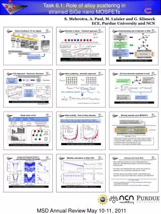
Strained Si C. C. Lee D91943026
WHY? • Improvement! • Short channel effect (SCE) • Gate dielectric thickness • Performance MOSFET mobility of the strained-Si devices is enhanced by 75% compared to that of the unstrained-Si control devices and the state- of-the-art universal MOSFET mobility.
HOW? • Lattice mismatch!
Tensile Strain • Energy Splitting Diagram
Strained-Si n-MOSFET Schematic illustration of a surface-channel Strained-Si n-MOSFET. From J.L. Hoyt, IEDM, 2002.
In-plane mobility(along [100],[010]directions) Mobility along [001] direction Electron Mobility for Strained-Si • In-plane mobility is enhanced
Hole Mobility for Strained-Si • In-plane and perpendicular mobility are enhanced
Mobility for Strained-Si µ=et/m* µ: Carrier mobility t: Scattering time constant m*: Effective mass
For electron & hole mobility: • Mobilities increase linearly with increasing strain when Ge <20% • Hole mobility will become to saturate at high Ge content (40%)
The SOI MOSFETs • The advantage of SOI MOSFETs • High carrier mobility in channel due to the reduced Coulomb scattering and effective normal field. • The reduction of parasitic capacitance of source/drain junctions. • Simple isolation process. • Small fluctuation of Vt due to low channel impurity concentration.
SiGe-On-Insulator • The advantage of strained-SOI MOSFETs • The SCE can be suppressed by thinning the thickness of Si. • Simple isolation process. • The reduction of parasitic capacitance of source/drain junctions. => High speed and low power consumption
Electron mobility characteristics of thick (circles) and thin (squares) strained-Si structures in various temperatures. The solid lines show the control-SOI data. Band diagram of strained-SOI MOSFET. From S. Takagi, IEDM, 2002.
Short Channel Effect From S. Takagi, IEDM, 2002.
Technology Issues: 1. Uniform buried oxide inside SiGe 2. Higher Ge content (~25%) of SiGe layer to obtain sufficient hole mobility enhancement T. Mizuno et al., TED 2002 Jan., p. 7.
To get uniform buried oxide: The temperature of SIMOX annealing must be higher than 1320ºC. • To get higher Ge content: The melting point of SiGe layer will be lower. => TRADE OFF Melting Point of SiGe and SIMOX annealing temperature condition
How to overcome the trade off? • New device structure: Strained-Si on double layer SiGe film with different Ge content. • New device process: The combination of SIMOX and ITOX
Strained-Si on Double Layer SiGe Film with Different Ge Content • Second-Si0.82Ge0.18/first-Si0.93Ge0.07 structure • The hole mobility enhancement is 30% as compared to the that of the universal mobility curve. • The second SiGe layer thickness was much thicker than the first SiGe one to realize higher effective Ge content.
Strained-Si on Double Layer SiGe Film with Different Ge Content
Strained-Si on Double Layer SiGe Film with Different Ge Content • Closed squares: Strained-SOI (double layer) (30% and 45% enhancement) • Close triangles: strained-SOI (single layer) • Open squares: Control SOI
The Combination of SIMOX and ITOX • High Performance FD and PD strained-SOI fabricated by the combination of SIMOX and ITOX technologies. • High Ge content [25%] • Without thick SiGe buffer layer • Electron mobility improvement 85% • Hole mobility improvement 50%
The Combination of SIMOX and ITOX • Key Points: • Uniform buried oxide formation inside SiGe and the relaxation of SGOI by SIMOX (dose 4E17, 1350°C) • The increase of Ge content and the buried oxide thickness by ITOX (1200 °C) • FD: 10nm SS on 36nm SGOI • PD: 28nm SS/2nd 288nm SiGe on SGOI
The Combination of SIMOX and ITOX • Peak electron mobility enhancement = 85% • Peak hole mobility enhancement =50%


![Approach: [1] Modified Valence Force Field to model phonons in strained Si nanowires .](https://cdn1.slideserve.com/1932078/strain-engineering-of-lattice-thermal-properties-in-silicon-nanowires-abhijeet-paul-gerhard-klimeck-dt.jpg)