Download
1 / 42
430 likes | 460 Views
User Manual Application Examples. Version of document: 2.01. Software CBox: v3. Language: English. Table of Content. Presentation Overview Digging a manhole Method 1: Using the bottom of the manhole as the reference

E N D
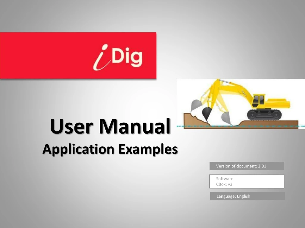
User ManualApplication Examples Version of document: 2.01 Software CBox: v3 Language: English
Table of Content • Presentation • Overview • Digging a manhole • Method 1: Using the bottom of the manhole as the reference • Method 2: Using (e.g.) a surveyor’sstake as the reference • Digging a 5m widemanhole • Digging a manholeusing a rotating laser • Method 1: Knowing the Laser Height • Method 2: Not knowingthe Laser Height • Digging a trench with 2% slope • Method 1: Using the bottom of the trench as the reference • Method 2: Using (e.g.) a surveyor’sstake as the reference • Digging a trench with 2% slopeusing a rotating laser • Method 1: Knowing the Laser Height • Method 2: Not knowing the Laser Height • Changing the elevation • Method 1: Workingwithout a rotating laser • Method 1: Workingwitha rotatinglaser • Moving the machine • Notes
Presentation Using this system on an excavator you may dig down to the desired depth with or without slope without the need of leaving the cabto control or a grade checker. With this system, capable to measure in three dimensions, you may measure the distance between two points located anywhere, such as the dimension of a trench, and the inclination of existing slopes. All measurements are taken from the two ends left, right and centre of the bucket blade (or teeth tip) until a point of reference. Sensors measure the angles of all moving parts (Chassis, booms, bucket) and the information is transmitted to the display in the cab. A step-stair LED display provides according informations. A patented system enables to install and calibrate the system in less than an hour without specific required know-how of machine control. Wireless technology makes it portable on each machine in your fleet.
Overview Change the View Default Zoom Laser Reference Top Viewwith Axes and Slopes 2nd Bucket View ActualDiggingHeight Zoom out Zoom in Actual Bucket Orientation Axis Alignment and Counter SmartTape Sensor Check HeightAlarm List of Buckets Slope Elevation Mode Enable/Disable Reach User Menu Change of Laser Height Move the Reference Quick Elevation Setting Laser Catch Delete the 1st Laser Catch Slope Setting Elevation Setting
DIGGING A MANHOLE Method 1: Using the bottom of the manhole as the reference
DIGGING A MANHOLE Method 1: Using the bottom of the manhole as the reference Place the tip of the bucket at the bottom of the trench and then press the symbol “Elevation" Enter '0' as the height (you are at the bottom of the manhole) then validate. The screen and the LED Display are now giving you real-time elevation informations. Note: After the first setting of elevation, a second button appears on the very right hand side: by clicking on it, you’ll set the last dialed-in elevation with one single click; here: 0,00m.
DIGGING A MANHOLE Method 2: Using (e.g.) a surveyor’s stake as the reference Digging a hole - Method 2: Usingsurveyorstake as reference Surveyor’s Stake 2,50m
DIGGING A MANHOLE Method 2: Using (e.g.) a surveyor’s stake as the reference Place the tip of the bucket on the surveyor’s stake and then press the symbol “Elevation" Enter « 2,50m » as your actualelevation and validate. The screen and the LED Display are now giving you real-time elevation informations. Note: After the first setting of elevation, a second button appears on the very right hand side: by clicking on it, you’ll set the last dialed-in elevation with one single click; here: 2,50m.
DIGGING A 5M WIDE MANHOLE Reference Point 5m
DIGGING A 5M WIDE MANHOLE Note: These steps occurein addition to the examples described previously. Click on the button “Enable/Disable Reach"on the left hand of the screen: If a 2D sensoris available, align the cabin along the manhole, and then click the alignment button: Place the tip of the bucket on the point of reference. Click on the “Reach Setting“ button: Depending on the working conditions, there are now two possibilities: Possibility 1: Possibility 2: Dial-in -5m Dial-in 5m
DIGGING A MANHOLE using a rotating laser Method 1: Knowing the Laser Height Laser Receiver Laser Height (2,21m + 2,50m) 2,21m 4,71m Reference Point 2,50m
DIGGING A MANHOLE using a rotating laser Method 1: Knowing the Laser Height Activate the 1st laser catch Click on « Set Laser Height » Dial-in « 4.71m » and validate Each time the machine gets moved, click on the button below to catch the laser beam again: Catch the laser beam • The laser height previously set is shown (4,71m) and the result of the calculation after the laser catch shows in this example that the bucket tip actually is 4,55m above grade.
DIGGING A MANHOLE using a rotating laser Method 2: Not knowing the Laser Height Laser Receiver Reference Point 2,50m
DIGGING A MANHOLE using a rotating laser Method 2: Not knowing the Laser Height Place the tip of the bucket on the point of reference and then enter '2.5m', finally confirm. Activate the 1st laser catch Click on « Bucket Height » Each time the machine gets moved, click on the button below to catch the laser beam again: • The bucket height is shown (2,50m) and the result of the calculation after the laser catch shows in this example that the Laser Height is 2,66m. Catch the laser beam
DIGGING A TRENCH with 2% slope Method 1: Using the bottom of the trench as the reference 2,00%
DIGGING A TRENCH with 2% slope Method 1: Using the bottom of the trench as the reference Click on « Slope Setting » Choose the direction of the slope on the bottomleft. Enter 2.00% and validate Note: If you’re using the 2D sensor, first align the cabin to the slope. Place the tip of the bucket at the bottom of the trench and then press the symbol “Elevation" Note: without 2D sensor, you have to dig parallel to the axis of the set slope. Turning the cabin causes an immediate error of calculation. Enter '0' as the height (you are at the bottom of the trench) then validate. Watch the on-screen instructions to follow the set slope.
DIGGING A TRENCH with 2% slope Method 2: Using (e.g.) a surveyor’s stake as the reference Reference Point 2,50m 2,00%
DIGGING A TRENCH with 2% slope Method 2: Using (e.g.) a surveyor’s stake as the reference Click on « Slope Setting » Choose the direction of the slope on the bottomleft. Enter 2.00% and validate Note: If you’re using the 2D sensor, first align the cabin to the slope. Place the tip of the bucket on the reference point and then press the symbol “Elevation" Note: without 2D sensor, you have to dig parallel to the axis of the set slope. Turning the cabin causes an immediate error of calculation. Enter ‘2,50m' as the height (you are 2,50m higher than the bottom of the trench) then validate. Watch the on-screen instructions to follow the set slope.
DIGGING A TRENCH with 2% slope using a rotating laser Method 1: Knowing the Laser Height Note: You must set the same slope in the rotating laser as in the iDig system and align it to the same axis. Laser Receiver 2,00% Laser Height (2,21m + 2,50m) 2,21m 4,71m Reference Point 2,50m 2,00%
DIGGING A TRENCH with 2% slope using a rotating laser Method 1: Knowing the Laser Height Click on « Slope Setting » Choosethe direction of the slope on the bottomleft. Enter 2.00% and validate. Note: If you’re using the 2D sensor, first align the cabin to the slope. Activate the 1st laser catch Dial-in « 4.71m », validate, and catch the laser beam. • The laser height previously set is shown (4,71m) and the result of the calculation after the laser catch shows in this example that the bucket tip actually is 4,38m above grade. Click on « Set Laser Height »
DIGGING A TRENCH with 2% slope using a rotating laser Method 2: Not knowing the Laser Height Laser Receiver Note: You must set the same slope in the rotating laser as in the iDig system and align it to the same axis. 2,00% Reference Point 2,50m 2,00%
DIGGING A TRENCH with 2% slope using a rotating laser Method 2: Not knowing the Laser Height Click on « Slope Setting » Choosethe direction of the slope on the bottomleft. Enter 2.00% and validate. Note: If you’re using the 2D sensor, first align the cabin to the slope. Activate the 1st laser catch Place the tip of the bucket on the point of reference and then enter '2.5m', confirm, and catch the laser beam. Click on « Bucket Height » • The bucket height is shown (2,50m) and the result of the calculation after the laser catch shows in this example that the Laser Height is 2,83m.
CHANGING THE ELEVATION Method 1: Workingwithout a rotating laser Reference Point 2,40m 2,50m 0,10m
CHANGING THE ELEVATION Method 1: Workingwithout a rotating laser Possibility 1 : Changing the elevation by changingdirectly the diggingdepth Enter a new height, 10cm HIGHER than the current height (2,50m 2,40m), then validate. The bucket is still on the original reference, but the digging depth has been DECREASED 10cm. Place the bucket on a known height (here 2,50 m), then click on “Elevation Setting". Possibility 2 : Changing the elevation by dialing-in an offset Click on the button 'Move the Reference' and then click the “Raise” button. Dial-in the offset, in this case 0,10m. The digging depth has been RAISED 10cm.
CHANGING THE ELEVATION Method 2: Workingwith a rotating laser 4,71m 4,61m 0,10m
CHANGING THE ELEVATION Method 2: Workingwith a rotating laser Possibility1: Change directly the diggingdepth Place the bucket on a known height (here 2,50 m), then click on “Elevation Setting". Enter a new height, 10cm LOWER than the current height (4,38m 4,28m), then validate. The digging depth has been RAISED 10cm.
CHANGING THE ELEVATION Method 2: Workingwith a rotating laser Possibility2: Change directly the Laser Height Click on « Set Laser Height » The bucket height / reference and Laser Height decreased by 10 cm. Enter a new Laser Height, 10cm LOWER than the current height (4,71m 4,61m), then validate.
CHANGING THE ELEVATION Method 2: Workingwith a rotating laser Possibility3 : Dial-in an offset Click on the button 'Move the Reference' Click the “Raise” button. The bucket height / reference and Laser Height decreased by 10 cm. Dial-in the offset, in this case 0,10m.
Moving the machine Job site view Job site reference point 20m trench to dig Existingground On this job site, a 20 m long trench, 2 m below the reference point on a sidewalk, has to be built.
Moving the machine Set reference 2m • Verify that no slope is set (0%) • Put the bucket tip on the reference point • Change the elevation • Enter 2m and validate
Moving the machine Start digging • Start digging following the indications of the system. • Your machine is not on an even surface, do not move the tracks!
Moving the machine Re-referencewith the bucket tip • To continue, move the machine forward • Put back the bucket tip on the reference point • Click the « Quick Elevation » button to re-reference the machine:
Moving the machine Re-referencewith the bucket tip • Continue digging, using the entire range of the elements to reduce the number of moves with the machine.
Moving the machine Re-reference with the bucket tip • As long as possible, put back the bucket on the reference point after the machine got moved • Click the « Quick Elevation » button to re-reference the machine: • And continue to work
Moving the machine Reference point out of reach of the bucket tip !!! • Now, you are too far away from the reference point. • Without rotating laser, you may re-reference on the ground (on a supposingly good elevation), but on long distance inaccuracies may add-up. • It’s time to use a rotating laser!!!
Moving the machine Reference point out of reach of the bucket tip 1m 2m • Setup the rotating laser. • Measure the elevationdifferencebetween the laser plane and the reference point. • In thisexample, the elevationdifference to the reference point is 1,00m, PLUS 2,00m elevationdifference to the ground, makes a total of 3,00m.
Moving the machine Reference point out of reach of the bucket tip The laser function is available but not yet initialized. Click the « 1st Laser Catch » button Click on “Set Laser Height” • Note: • If no laser button is visible, then the laser receiverneeds to be calibrated. • If several laser buttons are visible, then there is an “old” 1st laser catch existing. Delete this “old” catch to initialize a new 1st laser catch:
Moving the machine Reference point out of reach of the bucket tip 3 • Enter the Laser Height: • « 3,00m » and validate. • Now catch the laser beam and click on « Next ». Note: If the 'AutoCatch' option is enabled you do not need to click “Next”.
Moving the machine Reference point out of reach of the bucket tip 1m • You’re now able to re-reference each machine move by catching again the laser. • You may continue digging.
Moving the machine Each time you moved the machine… 1m • You need to moveagain. • The Laser Heightisalready set & defined.
Moving the machine Each time you moved the machine… • After the machine got moved, make another laser catch • Catch again the laser beam • The machine move gotcompensated
Notes : 1D mode and 2D mode In 1D mode, the measures are good for a single cabin position. This mode is suitable for the realization of single slope trenches. The measures are relevant ONLY in the axis of the trench. Any rotation of the cabin may cause an error, depending on the inclination of the excavator. When level (horizontal) areas are made, the error caused by the rotation of the cabin may be easily removed by using an additional sensor installed on the chassis. In 2D mode, a triple sensor measures the complete direction of the cabin, allowing total freedom of movement of the cabin. In this mode, the system allows to work on areas with dual slope. Combined with a tilt bucket sensor, the system helps the user to adopt the ideal angle of the bucket in relation to the desired slope. For large areas, each change of location of the machine may be compensated using the dipper stick sensor: It has a laser receiver inbuilt and after each laser catch the previous height change of the machine’s body gets compensated.