Download
1 / 38
380 likes | 384 Views
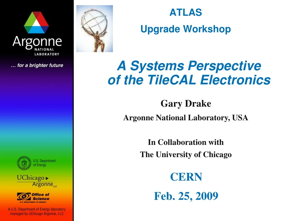
A Systems Perspective of the TileCAL Electronics. Gary Drake Argonne National Laboratory, USA In Collaboration with The University of Chicago. ATLAS Upgrade Workshop. CERN Feb. 25, 2009. General System Guidelines and Goals for the Upgrade.

E N D
A Systems Perspectiveof the TileCAL Electronics Gary Drake Argonne National Laboratory, USA In Collaboration with The University of Chicago ATLAS Upgrade Workshop CERN Feb. 25, 2009
General System Guidelines and Goals for the Upgrade • Primary Motivation: Improve radiation hardness of electronics • Basically all of on-detector electronics must be replaced… • Improve Reliability • Reduce complexity of on-detector electronics • Move digital signal processing to USA15 • Move pipelines and data storage to USA15 • Send digitized data off detector without trigger Data Push • Probably all of back-end electronics to be replaced • Connectors • Reduce drastically the number of connections & interconnects • Improve reliability and robustness of connectors • Reduce number of boards & board interconnects (daughter boards, etc) • Add redundancy to prevent single-point failures • LVPS • FPGA firmware
General System Guidelines and Goals for the Upgrade (Continued) • Perform L1 Trigger digitally; eliminate analog signal processing • Pile-up Issues • Pre-samples? • Additional digital filtering? • Both L1 Trigger and DAQ… • LVPS system • Generally reduce complexity of system • Reduce numbers of voltages to generated • Eliminate sensitivities to IR drops • Eliminate need for tight regulation • Use “point-of-load” regulators CERN rad-hard regulators • Implement redundancy • Cable Plant • Eliminate analog cables • Reduce/eliminate copper cables optical fiber • Use GBT for com link “ATLAS standard?” …Plus specific subsystem improvements…
Outline of Talk • A Conceptual Implementation of the TileCAL Electronics System • Deeper Look at Subsystems • Performance Requirements (just the primary aspects…) • Implementation Objectives • Conceptual Implementation • R&D Issues • Necessary Next Steps “A well-designed system composed of different components is one wrought together by careful thought and sheer will to work in harmony.” Attempting to answer the question: How do the TileCAL subsystems fit together from an engineering perspective?” Disclaimer: Most of the ideas in this presentation are those of others. The new part: How these subsystems could fit together…
A Conceptual Implementationof the TileCAL Electronics System On Detector USA15 Digital @ 40 MHz Front End Board anode signal CLK & CTRL Readout Interface Board Optical Fiber PMT DATA LV POWER HV TDAQ Interface, Timing & Trigger, & DCS Interface Bulk 200 VDC LVPS KEY: PMT Block Front End Board Bulk HV LVPS Readout Interface Board HV Distribution Board Back End Interface Bulk HV HV Distribution Board Optical Fiber
PMT anode signal HV in The PMT Block • Performance Requirements • Basically no change - PMT not envisaged to change • Gain ~1E5 @ ~700V • Dark current ~50 pA • Require programmable adjustment to HV delivered to PMT • Connectors • Anode connector OK • HV connector OK • R&D Issues • Standing current in HV divider OK? • Active divider? Work in progress at Clermont Ferrand…
Digital @ 40 MHz Front End Board anode signal CLK & CTRL DATA LV POWER The Front End Board To / From Readout Interface Board • Performance Requirements (partial listing) • 20 MeV – 1.3 TeV (12 fC – 800 pC) 16 bits dynamic range • Noise: < 24 fC (2 counts) • Pulse shaping – 7 points/event, 2% uniformity in transfer function • Integral nonlinearity: < 2 ADC counts • Differential nonlinearity: < 1 lsb • On-board charge injection – 1% uniformity, 0.1% repeatability • Radioactive source current monitor – 0.2% uniformity From PMT
Digital @ 40 MHz Front End Board anode signal CLK & CTRL DATA LV POWER The Front End Board To / From Readout Interface Board From PMT • Implementation Objectives (partial listing) • Front-end board replaces 3-in-1 Card • On-board digitization • Send digital data out of board, synchronous with BC • Keep analog signal processing local • Noise performance in present system is acceptable new system should not be worse • Reduce number of voltages & magnitudes of voltages • Use +/-10V input power • Use local rad-hard “Point-of-Load” regulators • Redundant power supplies? • Simple digital interface (parallel cable, 40 MHz data rate)
A Conceptual Implementation of the Front End Board Front End Board – 1/PMT – Replaces 3-in-1 Card To / From Readout Interface Board “Plan A” Preamp Hi Gain ADC 12 Bit Shaper Data Selector & Output Driver Digital @ 40 MHz Preamp Lo Gain ADC 12 Bit anode signal DATA PMT 1 ADC Imon CONTROL DAC CAL 16 Bit Timing Timing LV POWER POL REGs POL REG = “Point of Load” Regulator Plan A: Passive shaper, discrete parts, modest extrapolation from present system, Option: Incorporate ADCs into front end Actively being pursued by the Chicago Group
Preamp Hi Gain ADC Shaper 12 Bit Data Selector & Output Driver Preamp Lo Gain ADC Shaper 12 Bit ADC Imon DAC CAL 16 Bit Timing Another Conceptual Implementation of the Front End Board Front End Board – 1/PMT – Replaces 3-in-1 Card To / From Readout Interface Board “Plan B” ASIC Digital @ 40 MHz anode signal DATA PMT 1 CONTROL Timing POL REG = “Point of Load” Regulator LV POWER POL REGs Plan B: How much functionality can be incorporated into the custom chip and still obtain desired performance? Subject of R&D effort (see ASIC talk)
Conceptual Implementation of the Front End Board (Cont.) • Connectors • 3 connectors: Should be able to define these, independently of ASIC Front End Board – 1/PMT To / From Readout Interface Board Digital @ 40 MHz Ribbon Cable PCB Header DATA anode signal PMT 1 Front End Circuitry CONTROL 3-pin Timing Power Connector LV POWER POL REGs POL REG = “Point of Load” Regulator
Digital @ 40 MHz Front End Board anode signal CLK & CTRL DATA LV POWER Conceptual Implementation of the Front End Board (Cont.) To / From Readout Interface Board From PMT • Connectors (Cont.) • Can be realized with (1) 34-pin & (1) 40-pin ribbon cables • Could reduce pin count by using a serial DAC digital noise?...
Digital @ 40 MHz Front End Board anode signal CLK & CTRL DATA LV POWER The Front End Board (Cont.) To / From Readout Interface Board • R&D Issues • Discrete implementation • Shaping time? • Noise performance of 1st preamp? • Rad-hard parts? • ASIC implementation • Can performance specs be met? • Full specs in the works • Needs simulation starting • Can implement ADCs in chip? • Shaper transfer function • Charge injection implementation • Source monitoring: analog switches, digitization, data processing • Source monitor calibration implementation • Shaping • 80 MHz sampling? • ADC selection, clock noise, output drive • Digital noise abatement… • Connector selection…
The Readout Interface Digital @ 40 MHz CLK & CTRL Readout Interface Board Optical Fiber To / From Front End Board(s) DATA To / From USA15 • Performance Requirements • Receive ADC data from Front End Boards • @ 40 MHz, synchronous with Beam Crossing clock • Buffer data, pending transmission through optical fiber • Transmit control data to Front End Boards • @ 40 MHz, synchronous with Beam Crossing clock • Possibly only need 1 register – 16 bits for CAL DAC • Transmit timing signals to Front End Boards • Interface between LVPS power and Front End Boards • Support multiple Front End Boards… • Provide interface to USA15 • Optical cable • Implement redundant logic LV POWER From LVPS (on detector)
The Readout Interface Digital @ 40 MHz CLK & CTRL Readout Interface Board Optical Fiber To / From Front End Board(s) DATA To / From USA15 • Implementation Objectives • Use of GBT for optical interface? • Modular design • Self contained • Include diagnostic port, Built-In Self Test, … LV POWER From LVPS (on detector)
LVPS A Conceptual Implementation of the Front End Readout Interface Front End Boards Readout Interface Board – 1 per 4 PMTs Digital @ 40 MHz ADC Amp Shaper CLK & CTRL ADC analog PMT 1 Power Distribution & Conditioning ADC Imon DATA Cal DAC POL REG LV POWER ADC Amp Shaper CLK & CTRL ADC analog PMT 2 ADC Imon DATA Cal DAC POL REG LV POWER optical GBT FPGA To USA15 ADC Amp Shaper CLK & CTRL ADC analog PMT 3 ADC Imon DATA Cal DAC LV POWER POL REG ADC Amp Shaper CLK & CTRL ADC analog PMT 4 ADC Imon DATA Cal DAC POL REG LV POWER POL REG = “Point of Load” Regulator
Conceptual Implementation of the Front End Board (Cont.) • Physical Implementation in (Small) Drawer • 6 boards per small drawer (24 PMTs) • No two PMTs in dual-ended readout serviced by same Readout Interface Board Reliability • Two possible configurations (1 drawer, 24 PMTs): Readout Interface Boards Longitudinal arrangement of PCBs: OR PMTs with Front End Boards Lateral arrangement of PCBs: Red PMTs Red cables connect to red PCBs Blue PMTs Blue cables connect to blue PCBs
Conceptual Implementation of the Readout Interface Digital @ 40 MHz CLK & CTRL Readout Interface Board Optical Fiber To / From 4 Front End Boards DATA To / From USA15 • Data Format for GBT • Operate at 4.8 Gbps, 120-bit frame, 60 bits data • 1 frame / 25 nSec • Send data from 4 channels per frame • 12 bits per channel plus 2 range bit – front end chooses range to send… • Send integrator data in abort gaps • Use floating point: 12 bits + 2 range bits LV POWER From LVPS (on detector) Slow Controls Trigger & Timing Data Type Header Data – CH4 Error Correction Data – CH3 Data – CH2 Data – CH1 4 4 16 4 12+2 12+2 12+2 12+2 32
The Readout Interface Digital @ 40 MHz CLK & CTRL Readout Interface Board Optical Fiber To / From Front End Board(s) DATA To / From USA15 • R&D Issues • GBT? Or other optical link? Communication protocol? • Decoding of timing, trigger, control, & data • FPGA: Rad hard, error handling • Redundancy of logic? • Study of event reconstruction when samples occur across ADC ranges (also a front end issue…) LV POWER From LVPS (on detector)
The High Voltage Distribution Board From LVPS (on detector) Bulk HV – From USA15 HV Distribution Board • Performance Requirements • Current basic scheme is good • 350V adjustability per channel • Voltage read back over Slow Controls • Enable / disable over Slow Controls • Goal to reduce connectors, connections, plug-in boards… • Implementation Goals • One board per small drawer (24 PMTs) • Communication interface (GBT or other optical?) HV - To PMTs Optical Fiber Data Communication - To / From USA15
A Conceptual Implementation of the HV Dist. System HV Distribution Board – 1 per Drawer – Service 24 PMTs Bulk HV anode signal From USA15 Analog Control HV 8 Ch PMT 1 readback Opto Divider analog HV out analog control ADC MUX LV POL REG anode signal digital data Serial DAC HV DAC PMT 2 Opto Divider analog HV out LV analog POL REG LV POL REG Micro Controller optical GBT Analog Control 8 Ch To USA15 LV POL REG LV anode signal Analog Control 8 Ch On Detector HV PMT 24 Opto Divider analog HV out analog Power Conditioning LVPS LV POL REG cables inside drawer Based on the work of Clermont Ferrand…
The High Voltage Distribution Board From LVPS (on detector) Bulk HV – From USA15 HV Distribution Board • R&D Issues • Rad-hard parts • Interface to GBT • HV connectors & cables • Investigate failure modes, and consider ways to mitigate failures,,, HV - To PMTs Optical Fiber Data Communication - To / From USA15
Performance Requirements Receive 200 VDC from bulk supply in USA15 Produce +/- 10 VDC using buck converter architecture Regulation not crucial - ~5% sufficient if regulators are tolerant… Use point-of-load regulators Regulation more crucial - ~1% should be achievable Need to monitor voltages, current, & temperatures see LVPS talk Use GBT? Implementation Goals Reduce connections Improve connectors Eliminate sensitivities to IR drops Generally reduce complexity of system Reduce numbers of voltages to generated Eliminate need for tight regulation Implement redundancy Use CERN rad-hard regulators The LVPS System LVPS (on detector) Control & Monitoring Data Communication - To / From USA15 Optical Fiber To Front End Loads LVPS Bulk 200 VDC Bulk 200 VDC – From USA15 • Many R&D issues… See LVPS talk, this session
The TDAQ, Timing, & DCS Interface Optical Fiber TDAQ Interface • Performance Requirements – TDAQ Interface • Receive streaming data from drawers over high-speed link • De-serialize data stream • Format data for processing by subsequent stages • Data word, bunch crossing ID, event number, channel ID • Special formatting for calibration data… • Data Pre-Processing DPP • For physics data: • “Linearize” channel data (12-bit, 2 gains 16 bit)? • Use of look-up tables? • Signal reconstruction FIR filter produce 1 value of energy deposition per BC • Adaptive filtering… • Pile up de-convolution algorithm? • If read out both gains of FEE, select gain of interest • Special processing for calibration data: • Charge injection data • Source monitor data • Laser data • BIST data?
The TDAQ, Timing, & DCS Interfaces Optical Fiber TDAQ Interface • Performance Requirements – TDAQ Interface (continued) • Pre-process data for L1 Trigger L1CaloPP • Formation of trigger tower sums • Additional processing / filtering algorithms? • Formatting of data for L1CALO • Provide pipeline data storage pending L1 Trigger decision • ~5 mSec of total latency • Final processing of data for output (RODs…) • Additional filtering or processing?? Maybe different than for L1CALO… • Formatting of data, headers, IDs, etc. • Special features & functions • Processing of calibration data • Processing of diagnostic data
The TDAQ, Timing, & DCS Interfaces Optical Fiber DCS Interface • Performance Requirements – DCS Interface • Interface for control of front-end calibration operations • Charge injection; DC current injection • Setting of DACs • Control of calibration enable signals • Control of calibration-specific timing signals • Processing of monitor data • Source monitor (integrator) data • Voltages, currents, temperatures
The TDAQ, Timing, & DCS Interfaces Optical Fiber Timing & Trigger Interface • Performance Requirements – DCS Interface • Interface for 40 MHz Beam Crossing Clock • Interface for Bunch Crossing ID – served to FEE • Interface for trigger accept/reject (not needed in new FEE…) • Interface for special calibration timing signals
The TDAQ, Timing, & DCS Interfaces TDAQ, Timing & Trigger, & DCS Interfaces Optical Fiber • Implementation Goals • Use optical fiber between back-end interface and front-end interface, that handles data, timing & trigger, & slow controls • GBT development at CERN looks promising… • Merges these three very different functions into a single link • Implement with new generation of instrumentation crate • 33 MHz backplanes will not do the job anymore… • ATCA or mTCA look promising mesh networks See talk by Mike Huffer • Naming Convention: • TDAQ Interface, Timing Interface, DCS Interface Detector Interface
A Conceptual Implementation of the Detector Interface • Thoughts from Alberto Valero – November Workshop, 2008: Architecture 1a Architecture 1b Architecture 2
A Conceptual Implementation of the Detector Interface • Thoughts from Norman Gee – November Workshop, 2008: • The important functionality is defined … Is more needed? • Is timing skew adjust important? • Suggestion: Use adaptive digital filter techniques to deal with timing skew • Would make system more robust, less system infrastructure burden • Should be possible if have enough data points… • Needs study… • Huge overhead for a system…
A Conceptual Implementation of the Detector Interface Optical Fiber From Timing System Network Control L2 Fabric Timing Interface RX L2 Trigger Switching Network Optical Fiber From Detector 4 PMTs Pipeline GBT Interface L2 Output Processing DPP GBT L1CaloPP 6 Inputs (24 PMTs) Pipeline L1 Output Processing GBT Interface DPP GBT L1CaloPP L1 Trigger Switching Network From DCS (Network) Network Control L1 Fabric TX RX DCS Interface • Detector Interface Board – 1 ATCA Board • Receives 6 Data Fibers, 4 PMTs/Fiber 24 PMTs 1 Small Drawer • The ROD has been absorbed…
The Detector Interface Optical Fibers L1 Trigger From Timing System Detector Interface From Detector • R&D Issues (Only a partial list – There are many more…) • GBT? Or other optical link? Communications protocol? • Data formatting from detector? • New timing distribution system ATLAS-wide Interface requirements? • New trigger distribution system ATLAS-wide Interface requirements? • New DCS ATLAS-wide Interface requirements? • Study of bi-gain calibration & linearization • Study of algorithms to reconstruct data in the presence of pile up • Study of algorithms to reconstruct data with timing skew • L1 CALO pre-processing requirements? • L2 pre-processing requirements? • What will the trigger network fabrics be? • Data rate calculations • How to implement trigger rejects? • Error handling? • Diagnostics? • How will calibration routines work? How to load LUTs? L2 Trigger To/From DCS System
A Conceptual Implementationof the TileCAL Electronics System Revisited On Detector USA15 Digital @ 40 MHz Front End Board anode signal CLK & CTRL Readout Interface Board Optical Fiber PMT DATA LV POWER HV Optical Fiber Detector Interface LVPS Bulk 200 VDC KEY: PMT Block Front End Board Bulk HV LVPS Readout Interface Board HV Distribution Board Back End Interface Bulk HV HV Distribution Board Optical Fiber
Necessary Next Steps • Selection of basic system architecture subsystem identification • Factors: • Performance • Flexibility • Strengths of groups • High-level simulations • Specifications for all subsystem components • Performance specifications (for engineers!) • Subsystem interconnectivity • I/O protocols, required signals • data formats • data rates • Connectors & cables • Voltages, currents, power • Physical size • System-level simulations – subsystem functionality
Necessary Next Steps (Cont.) • Selection of critical components • Rad-hard parts • Develop testing program • Testing support for all subsystems • ASICs • Extensive simulations required • Prototype development • Rad-hard testing • Connectors • Project Execution Plan • Basic circuit design • Simulations • Prototype development • Prototype testing • Small system tests Vertical slice test crucial before the PRR crucial… • Test beam? A lot of effort, but we find the bugs before production… • Production Readiness Review
The Readout Interface • Data Format for GBT (Cont.) • Why is only (1) 12-bit, floating point value needed per crossing? • On average, a given channel will have underlying events (pileup) • Current scheme uses 7 samples @ 40 MHz to reconstruct pulse • Pileup will cause confusion in reconstruction algorithms if all 7 samples are required to be on the same range • For event reconstruction, if the calibration between ranges is good, then can obtain good reconstruction ADC ADC ADC 4095 65535 65535 X64 X 16 X1 X64 Q Q Q 800 pC 800 pC 13 pC 13 pC 800 pC 13 pC • Technique used successfully in CDF, MINOS, & CMS QIEs
The Readout Interface • Data Format for GBT (Cont.) • How to live with (1) 12-bit, floating point value per crossing • Key points: • Have good 12-bit ADCs (stable gain & offset, good linearity) • Keep ADC overlap regions away from very ends of range • Have a good charge injection system 16 bit • Use Look-Up Tables in Back End to “linearize” the floating-point data • Develop routine for performing charge injection