Download
1 / 45
450 likes | 534 Views
CLIC Post-Collision Line and Dump. Edda Gschwendtner, CERN. for the Post-Collision Team

E N D
CLIC Post-Collision Line and Dump Edda Gschwendtner, CERN for the Post-Collision Team Rob Appleby (CERN & Cockcroft Institute), Armen Apyan (CERN), Barbara Dalena (CERN), Konrad Elsener (CERN), Arnaud Ferrari (Uppsala University), Thibaut Lefevre (CERN), Cesare Maglioni (CERN), Alessio Mereghetti (CERN), Michele Modena (CERN), Mike Salt (Cockcroft Institute), Jan Uythoven (CERN), Ray Veness (CERN), Alexey Vorozhtsov (CERN)
2 2 Outline • Introduction • Absorbers and Intermediate Dump • Magnet System • Background Calculations to the IP • Main Beam Dump • Luminosity Monitoring • 500GeV/18.6mrad Option • Summary E. Gschwendtner, CERN
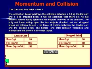
Beam dump Beam dump post-collision line 20mrad beam1 beam2 detector Post-Collision Line E. Gschwendtner, CERN CLIC meeting, 5 Nov. 2010
4 4 Some Numbers 50 Hz repetition rate 156ns bunch train length 3.7E9 e/bunch 312 bunches/pulse 14MW beam power • e+e- collision creates disrupted beam • Huge energy spread, large x,y div in outgoing beam total power of ~10MW • High power divergent beamstrahlung photons • 2.2 photons/incoming e+e- 2.5 E12 photons/bunch train total power of~4MW • Coherent e+e- pairs • 5E8 e+e- pairs/bunchX • 170kWopposite charge • Incoherent e+e- pairs • 4.4E5 e+e- pairs/bunchX 78 W E. Gschwendtner, CERN
5 5 Design Considerations • Transport particles of all energies and intensities from IP to dump • Diagnostics (luminosity monitoring) • Control beam losses in the magnets • Minimize background in the experiments • Stay clear of the incoming beam • Consequences • Large acceptance • Collimation system • Main dump • Beam diagnostic system E. Gschwendtner, CERN
ILC style water dump intermediate dump carbon based absorbers 1.5m side view C-shape magnets 6m 315m 4m 27.5m window-frame magnets 67m 6 6 Baseline Design A. Ferrari, R. Appleby, M.D. Salt, V. Ziemann, PRST-AB 12, 021001 (2009) • Vertical chicane • Separation of disrupted beam, beamstrahlung photons and right-sign charge particles from coherent pairs and particles from e+e- pairs with the opposite sign charge particles • Intermediate dumps and collimator systems • Back-bending region to direct the beam onto the final dump • Allowing non-colliding beam to grow to acceptable size E. Gschwendtner, CERN
side view ILC type water dump beamstrahlung photons disrupted beam + right sign coherent pairs 1.5 TeV 90cm 300 GeV 210m to IP: 105m Baseline Design Collided 1.5TeV Beam at water dump 315m from IP Right sign coherent beam Beamstrahlung photons Disrupted beam E. Gschwendtner, CERN
Baseline Design Geometry fully implemented in SW tools to main dump C-shaped magnets intermediate dump window-frame magnets to IP absorbers
9 9 Magnet Protection Absorbers and Intermediate Dump E. Gschwendtner, CERN
Absorber Baseline Design 10 10 Intermediate dump (CNGS style): iron jacket, carbon based absorber,water cooled aluminum plates, 3.15m x 1.7m x 6m aperture: X=18cm, Y=86cm Magnet protection: Carbon absorbers: Vertical apertures between 13cm and 100cm E. Gschwendtner, CERN
11 11 Absorber Baseline Design Aperture dimensions tuned such that losses in magnets < 100W/m 170kW Opposite sign charge particles 1.9kW 0.7 kW 131kW 3.1kW Right sign charge particles 1kW 6.9kW • All opposite charge particles absorbed by upper part of dump • Right charge particles with energy >16% of nominal pass through 4kW 0.9kW 0kW Solutions for absorbers exist (see dumps in neutrino experiments: 4MW) E. Gschwendtner, CERN
12 12 Magnets E. Gschwendtner, CERN
Post-Collision Line Magnets 13 • Designed considerations: • average current density in copper conductor < 5 A/mm2. • magnetic flux density in magnet core is < 1.5 T. • temperature rise of cooling water < 20° K. • All magnets strength of 0.8 T • In total 18 magnets of 5 different types • Total consumption is 3.3MW M. Modena, A. Vorozhtsov, TE-MSC E. Gschwendtner, CERN
Magnets Mag2 Mag3 Mag4 14 C-type Mag1a (window frame type) incoming beam 54.1cm 49 cm 40.8 cm 34.3cm 20.1cm 11.1cm 5.1cm spent beam Inter- mediate dump Mag1b Mag1a C- type 38m 46m 27.5m 30.5m 54m 67m 75m E. Gschwendtner, CERN
Window Frame Type Magnets Mag1a1b 10A/mm2 198kCHF 143kW 19.5cm distance to incoming beam 4.6A/mm2 280kCHF 65kW 5.1cm distance to incoming beam M. Modena, A. Vorozhtsov, TE-MSC E. Gschwendtner, CERN
Vacuum System 16 16 E. Gschwendtner, CERN E. Gschwendtner, CERN CLIC meeting, 5 Nov. 2010
Vacuum System Less demanding pressure requirement in the medium vacuum range (required pressure TBC), allowing for a conventional un-baked system design. Requires a high pumping speed due to the large surface area and beam-induced outgassing. A combination of sputter-ion, turbo-molecular and mechanical pumps will be used. stainless steel vacuum chambers in stepped or conical forms inside the magnetic and absorber elements. Absorbers are outside the vacuum chambers windows upstream of the intermediate dump absorbers exit window separating the collider vacuum system from the main dump body Large diameter (~1m). 17 17 elliptical vacuum tube R. Veness, TE-VSC E. Gschwendtner, CERN E. Gschwendtner, CERN CLIC meeting, 5 Nov. 2010
18 18 Background Calculations to IP E. Gschwendtner, CERN
19 19 Background Calculations from Post-Collision Line to IP • Entire Post-collision line geometry implemented • Using Geant4 on the GRID • Neutron and photon background from absorbers and intermediate dump • Neutron and photon background from main beam dump Ongoing: M. Salt, Cockcroft Institute C-shaped magnets intermediate dump window-frame magnets absorbers E. Gschwendtner, CERN
IP 10m 20 20 Photon Background from First Absorber to IP From first absorber: 0.73 ± 0.05 photons/cm2/bunchX Backscattered photons at the entrance to the first magnet (s = 27.5 m) M. Salt, Cockcroft Institute E. Gschwendtner, CERN
Photon Background from Intermediate Dump to IP 21 21 Backscattered photons at the entrance to the intermediate dump (s = 67 m) From intermediate dump: 7.7 ± 2.6 photons/cm2/bunchX (without absorbers: 530 ± 20 photons/cm2/bunchX) • Intermediate dump contributes significantly to IP background • But 98% attenuation thanks to aperture restriction in the chicane M. Salt, Cockcroft Institute E. Gschwendtner, CERN
Background Calculations to IP • Preliminary results show that background particles at ‘outer edge’ of the LCD is low. • The detector yoke and calorimeter will further shield the vertex and tracker against • hits from background photons. • Even if additional absorbers are needed, space is available in the forward region between the detector (6m) and the first post-collision line magnet (27m) . Lumical BPM Spent beam QD0 Kicker Beamcal N.Siegrist, H.Gerwig
23 23 Main Beam Dump E. Gschwendtner, CERN
24 24 Main Dump • 1966: SLAC beam dump • 2.2 MW average beam power capacity • Power absorption medium is water • 2000: TESLA • 12 MW beam power capacity • Water dump E. Gschwendtner, CERN
Baseline Main Dump Design 2008: ILC 18 MW water dump Cylindrical vessel Volume: 18m3, Length: 10m Diameter of 1.8m Water pressure at 10bar (boils at 180C) Ti-window, 1mm thick, 30cm diameter baseline for CLIC 2010 main dump 15.0 mm thick Ti vessel 30.0 cm diameter window (Ti) 1.0 mm thick ILC type water dump Diameter 1.5 m Dump axis Length 10.0 m 25 25 25 E. Gschwendtner, CERN CLIC meeting, 5 Nov. 2010
26 26 CLIC Main Beam Dump • Uncollided beam: sx = 1.56mm, sy =2.73mm 5.6mm2 • Collided beam: Photons Disrupted beam Coherent beam Collided 1.5TeV Beam at water dump 315m from IP Right sign coherent beam Beamstrahlung photons Disrupted beam E. Gschwendtner, CERN
Particle Distribution at the Beam Dump Entrance 27 27 Disrupted beam Coherent beam Photons 10-3 10-4 10-3 0mm 0mm 750mm 0mm -750mm -750mm -750mm 27 Window Dump A. Mereghetti, EN-STI E. Gschwendtner, CERN
Energy Deposition in Main Dump 28 28 max ≈ 270 J/cm3 uncollided beam collided beam (x10) max ≈ 10 J/cm3 uncollided beam collided beam [J cm-3 per bunch train] [J cm-3 per bunch train] A. Mereghetti, EN-STI E. Gschwendtner, CERN
Main Dump Issues 29 • Maximum energy deposition per bunch train: 270 J/cm3 ILC: 240 J/cm3 for a 6 cm beam sweep • Remove heat deposited in the dump • Minimum water flow of 25-30 litre/s with v=1.5m/s • Guarantee dump structural integrity • Almost instantaneous heat deposition generate a dynamic pressure wave inside the bath! • Cause overstress on dump wall and window (to be added to 10bar hydrostatic pressure). dimensioning water tank, window, etc.. • Radiolytical/radiological effects • Hydrogen/oxygen recombiners, handling of 7Be, 3H Calculations ongoing E. Gschwendtner, CERN
Dump Hall - Tank - Geometry Version 2 ILC Beam Dump Surround Dump Tank with 50 cm Iron + ~200 cm Borcrete (Concrete + 5% Boron). Minimize volume of activated air. Tail Catcher inside Dump Tank. Small open area around windows for changer mechanism to be developed. Space Distribution of Steady State Water Temperature Beam spot, 6 cm sweep radius This plan can work. 50 0C water inlet, 2.5 m/s Max water temp 147 0C Insertion Beam Line Temp K Beam Line Magnets Inlet Outlet Shd2 - Borcrete Extraction Beam Line Shd1 - Borcrete Shd0 - Iron Sump CLIC08, CERN, 16 Oct 2008
31 31 Energy Deposition in CLIC Beam Dump Window • Titanium window: • 1mm thick, 30cm diameter, cooling on internal surface by dump water at 180°C Total deposited Power: ~6.3W max ≈ 4.3 J/cm3 uncollided beam collided beam max ≈ 0.13 J/cm3 uncollided beam collided beam A. Mereghetti, EN-STI E. Gschwendtner, CERN
Temperature Rise in CLIC Beam Dump Window • Temperature rise per 1 pulse: • DT=0.44°C • Stable temperature after 3-4 sec with DT=24°C C. Maglioni, EN-STI E. Gschwendtner, CERN
ILC Beam Dump Window Titanium window: hemispherical shape, 1mm thick, 30mm thick, single jet cooling • Maximal total power of 25 W with 21 J/cm3 • Maximum temperature rises to 57°C
Other Main Dump Window Issues 34 • Beam dump window needs stiffener, double/triple parallel window system, symmetric cooling, etc… to withstand • Hydrostatic pressure of 10bar • Dynamic pressure wave • Window deformation and stresses due to heat depositions Calculations ongoing E. Gschwendtner, CERN
Luminosity Monitoring 35 35 E. Gschwendtner, CERN
36 36 Luminosity Monitoring e+e- pair production Beamstrahlung through converter Produce charged particles Optical Transition Radiation in thin screen Observation with CCD or photomultiplier m+m- pair production V.Ziemann – Eurotev-2008-016 • Main dump as converter muons install detector behind dump • With a Cherenkov detector: 2 E5 Cherenkov photons/bunch Converter (1mm thick C) Small magnetic field (10-3 Tm) OTR screen (30mm diameter) E. Gschwendtner, CERN
Muons/cm2/bunch 37 37 First Results Muon distribution with E> 212MeV behind the beam dump and shielding A. Apyan, EN-MEF E. Gschwendtner, CERN
Muons/cm2/bunch 38 38 First Results Muon distribution with E> 50 GeV behind the beam dump and shielding A. Apyan, EN-MEF Calculations ongoing: Include Cherenkov counters in simulations produce non-perfect collisions and track particles through post collision line to see variations in luminosity detectors E. Gschwendtner, CERN
500 GeV c.m. Scenario 39 39 39 E. Gschwendtner, CERN CLIC meeting, 5 Nov. 2010
Photons: 19cm horizontal shift, but reduced in size 250 GeV 1.5 TeV 19cm shift x’max = ±0.6mrad y’max= ±0.3mrad 40 40 500 GeV c.m. /18.6mrad Option versus 3000 GeV c.m. / 20mrad Option Collided 1.5TeV Beam at water dump 315m from IP 80cm Right sign coherent beam Beamstrahlung photons Disrupted beam x’max = ±1.6mrad y’max= ±1mrad Proof of principle Impact of 500GeV c.m. scenario on post-IP design is minimal E. Gschwendtner, CERN E. Gschwendtner, CERN CLIC meeting, 5 Nov. 2010
41 Summary • Many new results achieved since last year • Conceptual design of the CLIC post-collision line exists: • Magnets • Intermediate dumps • Background calculations to the IP • Luminosity monitoring: First promising results • Beam dump: first results, calculations ongoing • Improve design on beam dump • Collaboration with ILC: ILC-CLIC working group on dumps? E. Gschwendtner, CERN
42 42 • Additional Slides E. Gschwendtner, CERN
Plus others ……….. IP Feedback Beamcal+ Lumical Anti-solenoid Vacuum QD0 quadrupoles Support tubes +Stabilization + prealignment
Summary of Energy Deposition in Main Dump 44 44 E. Gschwendtner, CERN
Prompt Energy Deposition - J/cm3/hour - Geometry V2 Even the rocks get hot! Plan View Muon Spoiler Hall Dump Hall Air Air DT ~ 2 deg C/hour Borcrete Granite Water Iron CLIC08, CERN, 16 Oct 2008