Download
1 / 23
290 likes | 474 Views
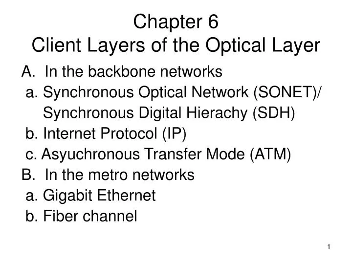
Chapter 6 Client Layers of the Optical Layer. A. In the backbone networks a. Synchronous Optical Network (SONET)/ Synchronous Digital Hierachy (SDH) b. Internet Protocol (IP) c. Asyuchronous Transfer Mode (ATM) In the metro networks a. Gigabit Ethernet b. Fiber channel.

E N D
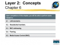
Chapter 6Client Layers of the Optical Layer A. In the backbone networks a. Synchronous Optical Network (SONET)/ Synchronous Digital Hierachy (SDH) b. Internet Protocol (IP) c. Asyuchronous Transfer Mode (ATM) • In the metro networks a. Gigabit Ethernet b. Fiber channel
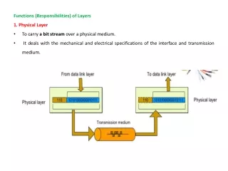
6.1.1 Multiplexing • The synchronous transport signal level-1 (STS-1) has the basic signal rate 51.84 Mb/s • The digital signal-0 has the rate 64 Kb/s
6.1.1 Multiplexing STM-1 (synchronous transport module-1) has the rate 155.52 Mb/s which is the same as STS-3
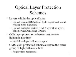
The path layer is responsible for end-to-end connections. The line layer is terminated at each intermediate line terminal (TM) or add/drop multiplexer (ADM). The line layer multiplexes a number of path layer connections onto a single link between two modes. The physical layer is responsible for actual transmission of bits across the fiber.
Section Overhead a. Framing (A1/A2):for delineating the frame. b. Section Trace (J0)/Section Growth (Z0): J0 is present in the first STS-1 in STS-N is used to carry an identifier.Z0 is present in the remaining STS-1s and its use is to be determined. c. Section BIP-8 (B1):This byte is located in the first STS-1 and is used to monitor the BER of each section (a bit interleaved parity)
d. Orderwire (E1):for maintenance (voice channel). e. Section User Channel (F1):for inserting additional user-specific information. f. Section Data Communication Channel (D1,D2,D3):for maintenance purposes such as alarms, and control.
Line BIP-8 (B2): To carry a bit interleaved parity check value of each STS-1 within the STS-N. APS channel (K1,K2): To provide a channel for carrying signaling information during automatic protection switching (APS). Line Data Communication Channel (D4~D12): To carry a line data communication channel for maintenance purposes such as alarms, monitoring, and control.
Path Overhead STS Path trace(J1):To carry a path identifier. STS Path BIP-8(B3):To carry a bit interleaved parity check value for the previous STS SPE. STS Path Signal label(C2):To indicate the content of the STS SPE (each type of signal mapped into a SONET STS-1). Path Status(G1):To convey the performance (error count) from the destination to the source.
6.1.4 SONET/SDH Physical Layer Application categories a. Interoffice connection (I) ≤ 2km b. Short haul (S) ≤ 15km at 1310nm ≤ 40km at 1550nm c. Long haul (L) ≤ 40km at 1310nm ≤ 80km at 1550nm d. Very long haul (V) ≤ 60km at 1310nm ≤ 120km at 1550nm e. Ultra long haul (U) ≤ 160km at 1550nm
6.1.5 Elements of a SONET/SDH Infrastructure • Terminal Multiplexer (TM) • Add/drop Multiplexer (ADM) • Digital Crossconnect (DCS)
6.4 Storage-Area Networks (SANS) • Enterprise serial connection (ESCON) • High performance parallel interface (HIPPI) • Fiber Channel