Download
1 / 34
350 likes | 384 Views
Understand OSI Data Link Layer's functions, protocols, and terminology for framing data, controlling media access, error detection, and connecting upper layers. Learn about MAC methods, protocol encapsulation, frame formats, and frame construction in networking.

E N D
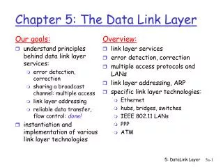
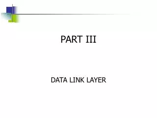
Details of OSI layers : Data Link Layer Instructor(s) F.M. Rashed Amin Shaila Sharmin M Abdullah Al Naser
OSI Data Link Layer Accessing the Media Exchange data over common media www.bdnog.org
Two basic functions: Allows the upper layers to access the media using framing. Controls how data is placed on the media and received from the media using media access control (MAC) anderror detection. Supporting and Connecting to Upper Layer www.bdnog.org
Data Link Layer Terminology www.bdnog.org
Layer 2 protocols specify the encapsulation of a packet into a frame and the techniques for getting the encapsulated packet on and off each media. • The technique is termed the Media Access Control (MAC) method. • Different media might require a different MAC method. Each media type encountered can have different characteristics. Controlling Transfer Across Local Media www.bdnog.org
Point-to-Point Protocol (PPP) High Level Data LinkControl Protocol (HDLC) EthernetProtocol Frame RelayProtocol Sample: Data Link Layer Frames www.bdnog.org
Protocol governs how to format a frame for use on that media Different protocols for different media Supporting and Connecting to Upper Layer Accept the frameDe-capsulate to a frameConstruct a new frame for the mediaForward the new frame www.bdnog.org
Controlling Transfer Across Local Media WAN Header WAN Trailer LAN Header Packet LAN Trailer LAN Header Packet LAN Trailer Different media… Different characteristics… Different MAC method… www.bdnog.org
Controlling Transfer Across Local Media The protocol can be configured on the device and determines the type of encapsulation (MAC method). Different media… Different characteristics… Different MAC method… www.bdnog.org
A Bridge between software and hardware. Layer is divided into two sublayers: 1. Logical Link Control(LLC) Logical address protocols 2. Media access control(MAC) Physical addressing and media requirements Connecting Upper-Layer services to Media www.bdnog.org
The description of aframe is the keyelement of each protocol. • Different protocols • require different information to function properly. • Which nodes are in communication with each other. • When communication between individual nodes begins and when it ends. • Which errors occurred while the nodes communicated. • Which nodes will communicate next. Creating a Frame www.bdnog.org
However, each Data Link Layer protocol is constructed using the same basic format. • It’s the contents that differ…. The Frame www.bdnog.org
The Frame www.bdnog.org
Contains the control information required by the protocol. • Some sample fields…… • Start of Frame • Source and Destination MAC Addresses • Priority/Quality of Service • Type/Length • Logical Connection Control • Physical Link Control • Flow Control • Congestion Control Framing: Role of the Header www.bdnog.org
Specific bit sequence that indicates to the receiving device that the frame starts here. For example: Framing: Role of the Header A code identifying the type of frame ORthe total length of the frame. upper layer service in the frame The source and destination MAC addresses. www.bdnog.org
The addresses used this layer are referred to as physical addresses. • They are the burned-in MAC addresses of the network device (PC: NIC, Router: Physical port). • They are only used for local delivery. • If the frame must be transported to another segment, the frame is re-encapsulated by the receiving device and forwarded. Addressing: Where the Frame Goes www.bdnog.org
Addressing: Where the Frame Goes OR send as a broadcast • The Data Link Layer protocol will define the addressing required to move the frame through the network. www.bdnog.org
Frame Check Sequence (FCS): Used to provide basic error checking, usually with a Cyclic Redundancy Check (CRC). - Sending device uses an algorithm on the bits of the header and data portions. - The resulting value is placed in the FCS field. - Receiving device does the same thing. - If the values match – no error. - If the values do not match – frame discarded. Framing: Role of the Trailer A specific sequence of bits that indicate the end of the frame. www.bdnog.org
As frames traverse the network, the source and destination addresses may change. • Source MAC – gets reset to the next device (routers) as it travels • Destination MAC – gets set to the next device in line (router or pc) • Source IP – NEVER CHANGES • Destination IP – NEVER CHANGES Traveling frames www.bdnog.org
Ethernet Protocol for LANs www.bdnog.org
Point-to-Point Protocol for WANs www.bdnog.org
Regulating the placement of data on the media is termed Media Access Control. Placing Data on the Media Media sharing: If and how the nodes share the media. Topology: How the connection appears to the Data Link Layer. www.bdnog.org
MAC for Shared Media : Two Basic Methods www.bdnog.org
What is CSMA(carrier sense multiple access)?? It reduced the chances of collision. It works on principle “sense before send”. • Listen to the channel • If channel sensed idle, transmit entire frame • If channel sensed busy, defer transmission by. 1. Persistent CSMA: Wait until channel is quiet and transmit immediately. If collision occurs, wait a random time and listen again (go to 1). 2. Non-Persistent CSMA: Wait a random time and listen again (go to 1). CSMA human analogy: don’t interrupt others! MAC for Shared Media : Two Basic Methods www.bdnog.org
CSMA/CD(carrier sense multiple access/collision detection) : • Sense using persistent method. • If it is free then start talking and Constantly monitor while sending frame. • If collision occur then , stop and talk after back off time. • Send a short jamming signal to notify a collision. • Energy levelin a channel can have three values: zero, normal and abnormal. • Used for traditional Ethernet. MAC for Shared Media : CSMA/CD www.bdnog.org
Advantages : 1- It detect collision within a short time . 2- More efficient than a simple CSMA. 3- It request node for transmission before sending any frame. 4- If collision occur then it send frame again at free time. 5- It avoid a wasteful transmission. MAC for Shared Media : CSMA/CD (Cont.) Disadvantages :1- It can’t reduce the possibility of collision between two nodes.2- Inappropriate for large networks.3-limited to 2500 meters, after this distance collision can’t detected. www.bdnog.org
CSMA/CA(carrier sense multiple access/collision avoidance) • 1. It was invented for wireless networks • 2. It avoid from collision • 3. It uses three stages to avoid from collision • IFS (Interframe space ) • Contention window • Acknowledgement • 4. Its similar to CSMA, but instead of only sending packets control frame (RTS= Request to send & CTS= clear to send) are also exchanged. MAC for Shared Media : CSMA /CA www.bdnog.org
Advantages : 1- When data is large then it reduce the collision chances. 2- It avoid from hidden terminal collision. 3- It control packets and send these packets to whom receiver wants to send. MAC for Shared Media : CSMA /CA (Cont.) Disadvantages :1- It is less efficient than a CSMA/CD 2- It can’t solve the problem of MAC Layer in wireless networks 3- Its difficult to avoid from collision in wireless network www.bdnog.org
Point-to-Point Connections: Type of communication. MAC for Non-Shared Media Full Duplex Half Duplex www.bdnog.org
Physical Topology: Arrangement of the nodes and the physical connections between them . Logical Topology: The way a network transfers frames among nodes. The use of virtual connections between the nodes regardless of the actual physical connection. • Point-to-Point • Multi access • Ring Logical Topology vs Physical Topology www.bdnog.org
Concerned with full or half duplex. Point-to-Point Logical Topology www.bdnog.org
Enables a number of nodes to communicate using the same shared media. A sends to E Multi-access Logical Topology Check for other transmissions Media available X Transmit X X I’ll wait…… Media NOT available Check for other transmissions B needs to send to D www.bdnog.org
Each node receives a frame in turn. If it is not addressed to the node, it passes it on. Ring Logical Topology Yes Is it for me? No Is it for me? A sends to D No Is it for me? www.bdnog.org