Download
1 / 13
140 likes | 343 Views
What do we have? We are using a Gaussian beam to generate the point spread function. Which parameters are we using? Numerical aperture Wavelength Shear bias. Using product of 2D convolution to solve constant phase problem. Using different objects: Single binary object

E N D
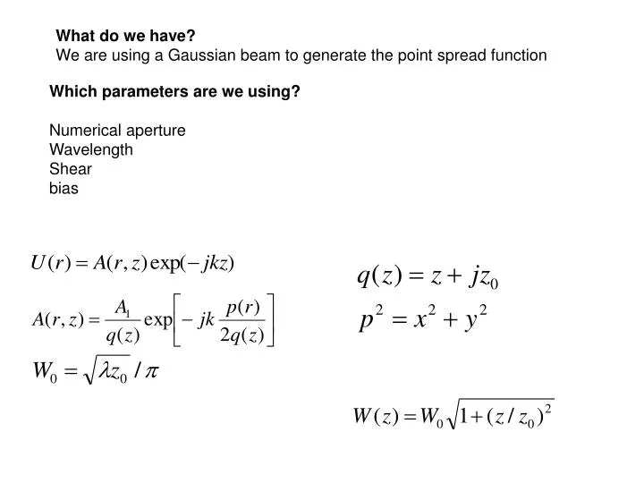
What do we have? We are using a Gaussian beam to generate the point spread function Which parameters are we using? Numerical aperture Wavelength Shear bias
Using product of 2D convolution to solve constant phase problem • Using different objects: • Single binary object • Object with constant phase • Object with different slices • bead in oil
Images look good for a single Binary phase object using the product This is the image at xz plane Using the PSF with 150 stacks
Using object with different slices Slice at z=30 z 20 slices x Using PSF with 80 slices Images look good Slice at z=80
Xz plane, dz=0.5 microns Xy image xy plane dx=0.5 microns
Comments and next steps • Binary phase data look similar to real data, xy and xz planes • Data for bead in oil look fine in xy plane, but it is not clear • in xz plane. • Comment1: • The way that we are modeling the images is assuming that the condenser aperture is closed. It should be a reason why bead’s images model doesn’t look like real image. • Comment2: • the product of 2D convolution work better that using 3D convolution. • Consider a validation of the model using a real images could be not able, because we are considering coherent illumination
Deconvolution and Reconstruction References about 3D DIC imaging model and 3D Deconvolution • 3D DIC imaging model • The more recent work is by Kagalwala and Kanade ,2003 • this work shows a computational model. • 3D deconvolution • Several references are found in this field, but they are not applied to DIC, • also experimental PSF is used in most of the cases. • This references are focused in reconstruction applying optimization techniques and typical algorithms like LS and MLEM.
Preliminaries deconvolution experiments The deconvolution algorithms presented in sveral publications are available in XCOSM. Generate PSF using real parameters Use modified general deconvolution methods for DIC iamges. Reconstructs 3D objects. Corrections algorithms are also included. Several references had used this software Things to do: Apply these method and analyze this result to learn more about DIC images
Find new methods to model DIC images? Description Defocused transfer function for partially coherent microscope and applicationTo phase retrieval. Sheppar,2004. Application to weak objects and it works well for thin objects. Next and current steps: Understanding the method, using previous references. See if it can be applied to DIC.
Recontruction methods and phase retrieval Reconstruction algorithms establish relation between the frequency content of the object and the transfer function of the system, which eliminate frequencies components that appear using 3Dconvolution in the frequency domain. 3D Transfer function is already defined for DIC. Coswell and Sheppard, 1992 Previous models for 3D transfer function present problems with high Numerical apertures. 3D vectorial optical transfer function has shown work successfully in General microscopy systems. Phase imaging using differential interference contrast microscopy M.R. Arnison,2003 A 3D optical transfer function suitable for arbitrary pupil functions Arnison, Sheppard ,2002
C. Preza, M. I. Miller, L. J. Thomas, Jr., and J. G. McNally. "Regularized Linear Method for Reconstruction of Three-Dimensional Microscopic Objects From Optical Sections". J. Opt. Soc. Am. A, 9(2):219-228, February 1992. C. Preza, M. I. Miller, J. A. Conchello. "Image Reconstruction for 3-D Light Microscopy with a Regularized Linear Method Incorporating a Smoothness Prior". in Biomedical Image Processing and Biomedical Visualization, R. S. Acharya, D. B. Goldgof, Eds., Proceedings of IS&T/SPIE's Symposium on Electronic Imaging: Science & Technology, pp. 129-139, 1993. J.-A. Conchello, and J. G. McNally. "Fast Regularization Technique for Expectation Maximization Algorithm for Optical Sectioning Microscopy". Monograph #591, Biomedical Computer Laboratory, Institute for Biomedical Computing, Washington University in St. Louis.
Real data xz yz
Next steps: • Consider similar model for QTM and try some simple simulations. Since QTM is coherent . • Since one of the goals is try to apply inversion methods, we should consider try simple experiments to see the behavior applying inversion techniques to DIC images with the current model or try to improve the model. References about 3D DIC imaging model and 3D Deconvolution • 3D DIC imaging model • The more recent work is by Kagalwala and Kanade ,2003 • this work shows a computational model. • 3D deconvolution • Several references are found in this field, but they are not applied to DIC, • also experimental PSF is used in most of the cases. • This references are focused in reconstruction applying optimization techniques and typical algorithms like LS and MLEM.