Download
1 / 16
160 likes | 332 Views
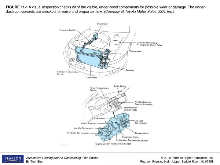
FIGURE 11-1 A visual inspection checks all of the visible, under-hood components for possible wear or damage. The under-dash components are checked for noise and proper air flow. (Courtesy of Toyota Motor Sales USA, Inc.).

E N D
FIGURE 11-1 A visual inspection checks all of the visible, under-hood components for possible wear or damage. The under-dash components are checked for noise and proper air flow. (Courtesy of Toyota Motor Sales USA, Inc.)
FIGURE 11-2 A drive belt should be replaced if it has any of the problems shown. (Courtesy of Dayco Products, Inc.)
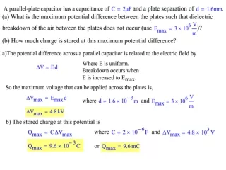
FIGURE 11-3 With the engine off, compressor clutch inspection includes a check for air gap between the clutch plate and pulley. The hub and compressor shaft should rotate smoothly, without runout of the clutch plate. (Courtesy of Chrysler LLC)
FIGURE 11-4 Hose inspection can be difficult in tight quarters. Check for cracks and cuts and squeeze the hose to check for hardening or excessive softness. Squeeze the hose close to the ends to check for softening. (Courtesy of The Gates Rubber Company)
FIGURE 11-5 Inspection includes a check for proper blower operation through each of the speeds (a) and air discharge from each location for the different functions (b). (Courtesy of Chrysler LLC)
FIGURE 11-6 With the engine running, compressor clutch inspection includes a rapid engagement as the clutch wire is connected, a clean disengagement with no drag as the wire is disconnected, smooth and quiet pulley operation, and very little runout of the pulley.
FIGURE 11-7 When a system is operating properly, the suction line to the compressor should be cool, and the discharge line should be hot to very hot (a). The liquid lines should also be hot (b). (Courtesy of Chrysler LLC)
FIGURE 11-8 A trouble tree can be followed to determine the cause of the problem (a). Note that some checks lead to further checks that are listed on the troubleshooting charts (b). (Courtesy of Zexel USA Corporation)
FIGURE 11-8 (CONTINUED) A trouble tree can be followed to determine the cause of the problem (a). Note that some checks lead to further checks that are listed on the troubleshooting charts (b). (Courtesy of Zexel USA Corporation)
FIGURE 11-9 A thorough diagnostic procedure follows steps like these to locate and repair problems the first time a vehicle is worked on.
FIGURE 11-10 Three problem diagnosis charts. Chart (a) shows the most probable and possible causes of a group of problems. Chart (b) shows the procedure for locating a noisy compressor problem. Chart (c) is a flowchart for locating an ATC problem. (a. Courtesy of Saturn Corporation; b and c. Courtesy of Chrysler LLC)
FIGURE 11-10 (CONTINUED) Three problem diagnosis charts. Chart (a) shows the most probable and possible causes of a group of problems. Chart (b) shows the procedure for locating a noisy compressor problem. Chart (c) is a flowchart for locating an ATC problem. (a. Courtesy of Saturn Corporation; b and c. Courtesy of Chrysler LLC)
FIGURE 11-10 (CONTINUED) Three problem diagnosis charts. Chart (a) shows the most probable and possible causes of a group of problems. Chart (b) shows the procedure for locating a noisy compressor problem. Chart (c) is a flowchart for locating an ATC problem. (a. Courtesy of Saturn Corporation; b and c. Courtesy of Chrysler LLC)
FIGURE 11-11 A foul smell from the A/C can be cured by spraying a cleaning solution or fungicide onto the evaporator to either clean it thoroughly or kill the bacteria. (Courtesy of Airsept, Inc.)
FIGURE 11-12 An electronic evaporator dryer (EED)/after-blow module can be connected into the blower motor circuit. It will operate the blower motor after the system is shut off to dry the evaporator and prevent bacterial growth. (Courtesy of Airsept, Inc.)