Download
1 / 27
300 likes | 449 Views
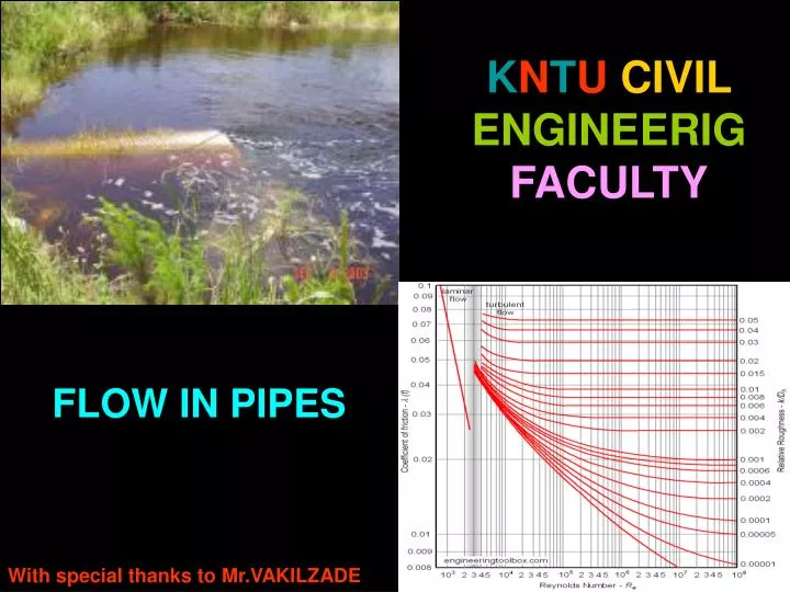
`. K N T U CIVIL ENGINEERIG FACULTY. FLOW IN PIPES. With special thanks to Mr.VAKILZADE. Velocity profile:. open channel. pipe. Friction force of wall on fluid. For pipes of constant diameter and incompressible flow.

E N D
` KNTUCIVILENGINEERIGFACULTY FLOW IN PIPES With special thanks to Mr.VAKILZADE
Velocity profile: open channel pipe Friction force of wall on fluid
For pipes of constant diameter and incompressible flow Vavg stays the same down the pipe, even if the velocity profile changes Vavg Vavg Conservation of Mass same same same
For pipes with variable diameter, m is still the same (due to conservation of mass), but V1 ≠ V2 D1 D2 m V1 V2 m 2 1
Definition of Reynolds number: Re < 2300 laminar 2300 ≤ Re ≤ 4000 transitional Re > 4000 turbulent
Hydraulic diameter: Dh = 4Ac/ P • Ac = cross-section area • P = wetted perimeter
Consider a round pipe of diameter D. The flow can be laminar or turbulent. In either case, the profile develops downstream over several diameters called the entry lengthLh. Lh/D is a function of Re.
Instantaneousprofiles Comparison of: laminar and turbulent flow
Laminar Turbulent slope slope w w w,turb > w,lam w = shear stress at the wall, acting on the fluid
w Take CV inside the pipe wall P1 P2 V L 2 1 Conservation of Mass
Conservation of x-momentum Terms cancel since 1 = 2 and V1 = V2
or Energy equation (in head form): cancel (horizontal pipe) V1 = V2, and 1 = 2 (shape not changing) hL = irreversible head loss & it is felt as a pressuredrop in the pipe
w = func( V, , D, ) = average oughness of the inside wall of the pipe
But for laminar flow, roughness does not affect the flow unless it is huge Laminar flow: f = 64/Re Turbulent flow: f = Moody Chart
i pipe sections j components Minor Losses: KL is the loss coefficient.
Energy Line (EL) and Hydraulic Grade Line (HGL) (Source: Larock, Jeppson and Watters, 2000: Hydraulics of Pipeline Systems)
Pipe Networks : • Pipes in series • Pipes in parallel
1 A 2 B 3