Download
1 / 17
170 likes | 191 Views
Bardac D rives. New Variable Frequency Drive for Solar Pumping. Solar Pumping. The E3 has been used successfully for basic solar pumping applications set in PI mode and using the DC Bus Voltage as the feedback.

E N D
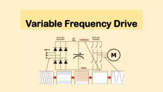
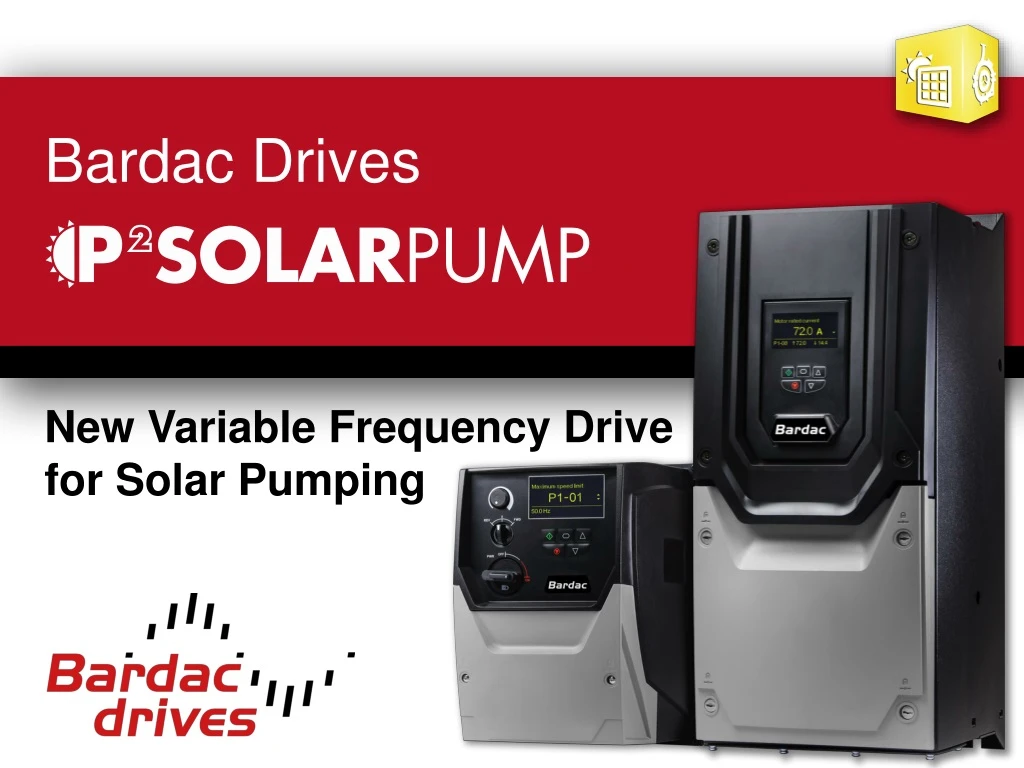
BardacDrives New Variable Frequency Drive for Solar Pumping
Solar Pumping • The E3 has been used successfully for basic solar pumping applications set in PI mode and using the DC Bus Voltage as the feedback. • This solution is slightly crude, but it works well and is generally a very cost effective solution. • Some applications require a more efficient solution and a premium product is necessary. • This requirement cased the demand for the P2 Solar Pump Drive.
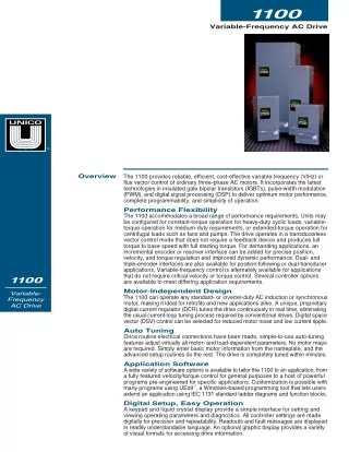
So what is the P2 Solar Pump Drive? • P2 hardware with modified Eco firmware which has all the pump functionality built in as well as the additional features of the solar pump drive. • Designed primarily to be connected directly to solar panels and operate a pump controlling the speed of the pump (load) based on the power available from the array. • PV Panels have an unique characteristic and it can be easy to collapse the Voltage of the array if too much power is taken from the array. • This has historically been achieved by setting the drive into PI mode and using the DC Bus Voltage as feedback. • On a real application, the P2 Solar Pump Drive has achieved 15Hz higher output frequency with the in-built MPPT (Maximum Power Point Tracking) than the traditional method of using the internal PI with DC-Bus Voltage feedback under equivalent conditions.
So what is the P2 Solar Pump Drive? • BardacDrives will sell a standard P2 drive to our partners. • Partners with service level access on OptiTools Studio will be able to convert the standard P2 to a P2 Solar Pump Drive. • P2 Solar Pump badges will be available to place on the front of the drive.
Some new terms and technology to understand • Solar Panel – Usually a panel has a nominal current and nominal voltage. • String - A number of panels are connected in series to get the required voltage. • Array - A number of strings are put in parallel to get the required current (or power). • Maximum Power Point Tracking (MPPT) – As the actual conditions change (clouds passing by, position of the sun in the sky), the array power characteristics change. The MPPT tracks the point of maximum power from the array by modulating the load on the drive.
Some new terms and technology to understand Basic Solar Panel I/V characteristics :
Some new terms and technology to understand Basic Solar Panel I/V characteristics : The short circuit current Isc, is the maximum current from a solar cell and results in zero voltage across the device.
Some new terms and technology to understand Basic Solar Panel I/V characteristics : The open circuit voltage Voc, is the maximum voltage from a solar cell and occurs when the net current through the device is zero.
Some new terms and technology to understand Basic Solar Panel I/V characteristics : Maximum Power Point For max output, we need to constantly adjust the motor speed to sit at the peak of the curve – this is what we call Maximum Power Point Tracking – continuously adjusting for optimum performance. • The maximum power point MPP is right on the knee of the I/V curve. • This makes it easy to collapse the panel voltage.
Some new terms and technology to understand I/V characteristics : • The panel voltage is affected a little bit with irradiance but the power output changes significantly. • This is why the MPPT algorithm is able to provide a higher output across a range of conditions than the historic method of using PID with DC Bus voltage as the feedback.
Daily Solar Power Curve – ‘Ideal’ • This bell-curve is a typical daily power curve for a solar array under cloud-free conditions.
Daily Solar Power Curve – ‘Ideal’ • This bell-curve is a typical daily power curve for a solar array under cloud-free conditions. • Some customers will want to maximise the pumping and as such will size the array much larger than the drive rating – above example with a 2.2kW drive with a 5kW array – on cloudier days the drive delivers a higher percentage of the power available, but for most of the day the drive is delivering it full rating. • This configuration is likely to suit the E3 application.
Daily Solar Power Curve – ‘Ideal’ • This bell-curve is a typical daily power curve for a solar array under cloud-free conditions. • Some customers will want to reduce costs and as such will size the array close to the rating of the drive – above example with a 4kW drive with a 5kW array – on cloudier days the drive frequently delivers less than its rating. • This is when the MPPT algorithm gives more benefit.
Some Basic Application Details • Designed for DC feed only – if a hybrid system is required for AC and DC (solar) supply then a contactor arrangement would be required – could be controlled by on-board PLC if external 24V available. • Majority of applications for pumping water from deep wells into water towers which can be used for irrigation by gravity feed. • Some applications for direct irrigation – pumping water from the well directly to the fields. • We cannot operate in PID mode for water pressure and with MPPT for maximum output from the array. • To prevent overpressure in this kind of situation, a pressure transducer can be connected to the drive but this will require a plc program to interface the measurement and create the required action. • This will be implemented in future firmware enhancements. • There is a PLC program that is currently being tested that will provide a second PI loop for pressure control – this basically will not increase the speed of the pump above the MPPT control, but can reduce the speed of the pump below the reference of the MPPT control if water pressure is achieved.
Some Basic Application Details • Array sizing and panel selection is not our responsibility but key factors to consider include: • Voc should be at the upper end of our operating voltage but MUST NOT exceed the drive operating voltage range. • 185 – 410Vdc / 345 – 800Vdc • Note that solar panel data is provided for standard conditions and high irradiance and cold temperatures can result in higher voltages than specified! • Recommended VMPP should be about 325Vdc (LV drives) and 565Vdc (HV drives). • The geographical location and the angle of the installed panels will greatly affect the power available. • The sun shining at 90 degrees to the panel (incident angle) provides far more energy than an incident angle of 60 degrees.
How do we differentiate our drivefrom the competition? • The efficiency of our MPPT algorithm means that we operate at and follow the knee of the P-V curve very accurately. • Our customers have indicated that we can deliver higher pumping rates than our competitors.
Remember!! The E3 is still a very viable solution for PV pumping and the P2 Solar Pump Drive is not intended to replace these applications! E3 General Purpose Lower Cost Solution P2 Solar Pump Drive High Performance Solution