Download
1 / 39
390 likes | 404 Views
NSTX-U. Supported by. NSTX Centerstack Fabrication Status. Coll of Wm & Mary Columbia U CompX General Atomics FIU INL Johns Hopkins U LANL LLNL Lodestar MIT Lehigh U Nova Photonics Old Dominion ORNL PPPL Princeton U Purdue U SNL Think Tank, Inc. UC Davis UC Irvine UCLA

E N D
NSTX-U Supported by NSTX Centerstack Fabrication Status Coll of Wm & Mary Columbia U CompX General Atomics FIU INL Johns Hopkins U LANL LLNL Lodestar MIT Lehigh U Nova Photonics Old Dominion ORNL PPPL Princeton U Purdue U SNL Think Tank, Inc. UC Davis UC Irvine UCLA UCSD U Colorado U Illinois U Maryland U Rochester U Tennessee U Tulsa U Washington U Wisconsin X Science LLC Culham Sci Ctr York U Chubu U Fukui U Hiroshima U Hyogo U Kyoto U Kyushu U Kyushu Tokai U NIFS Niigata U U Tokyo JAEA Inst for Nucl Res, Kiev Ioffe Inst TRINITI Chonbuk Natl U NFRI KAIST POSTECH Seoul Natl U ASIPP CIEMAT FOM Inst DIFFER ENEA, Frascati CEA, Cadarache IPP, Jülich IPP, Garching ASCR, Czech Rep James H. Chrzanowski and the NSTX Upgrade Team Princeton Plasma Physics Laboratory NSTX Upgrade Project Office of Science Review LSB B318 February 4, 2014
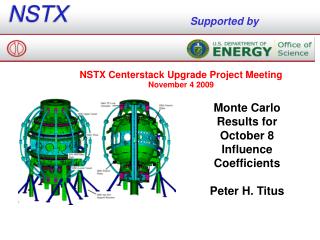
General Arrangement Umbrella Structure TF Flex Bus and Support Structure Centerstack Assembly Major Centerstack Components Outer TF Coils Vacuum Vessel
Upgraded Centerstack Components Inner PF1c Inner PF1b Inner PF1a Inner TF Bundle Plasma Facing Components Ohmic Heating Coil CS Casing Ceramic break assembly
Topics • Progress of the Centerstack since last review • Remaining risks and mitigation plans, Plans forward • Address charge question #1 Critical Path Construction Efforts: • Does the Project team have a realistic, executable schedule for Center Stack (CS) remaining construction efforts? • Does the project have adequate resources and the appropriate skills mix to execute the remainder of the project per the plan?
Center Stack Status Since Last Review • Inner TF Bundle • Complete • Centerstack Casing • Delivered and studs have been installed • OH Solenoid • Major tooling for OH solenoid has been delivered & commissioned • Aquapour and epoxy/glass base has been installed over TF bundle • First layer of OH solenoid has been wound • Completing layer transition 1 to 2 and resume winding layer 2 • Inner PF coils • PF1b coils have been completed
Involvement of ES&H Safety Department • The fabrication & assembly of the Centerstack is being performed by PPPL personnel at the laboratory. • Safetyis an important part of the PPPL culture • Safety is incorporated in all aspects of the development program- carryover to production • Industrial Hygiene(IH) & Construction Safety have participated in the planning and setup of the coil area • Job Hazard Analysis (JHA’s)are being developed for each procedure • Procedures: Clearly identify safety precautions for specific operations • Personnel protective equipment(PPE’s) being used • “Tool Box” Safety meeting held monthly with Technicians • Involvement with all safety groups
Progress- Raising the Full TF Bundle • Completed testing of TF Bundle • Raised TF Bundle to the vertical position in preparation for the application of the Aquapour. √ complete
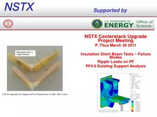
Progress- Installation of Aquapour Layer • Installation of Aquapour layer was successfully completed √ complete “Aquapour” is used as a temporary spacer that will be used to maintain 0.100 inch gap between the TF OD and OH ID surfaces. It is removed post VPI of OH coil
OH Solenoid Winding Facility • The OH Solenoid is being wound onto the Inner TF Bundle • Completed setup & commissioning of OH winding equipment in CS High Bay area
Tooling- OH Winding Station Pivot Beam OH Winding station fully commissioned Shops √ complete Copper Spools Cut-off saw & Braze Station Hydraulic Tension Unit Dual Taping Heads
Progress- Winding Preparations Epoxy/glass layer was applied over the Aquapour surface to provide a solid winding surface OH support structure was installed √ complete
Transfer TF to OH Winding Station • The TF bundle was transferred to the OH Winding station √ complete
OH Solenoid Fabrication- 1 • Wind the OH solenoid using approved drawings and procedure D-NSTX-IP-3385 • Four layers/ 880 turns/ (2) conductors in-hand • Co-wound turn to turn insulation (Kapton/glass) • In-line braze joints • Layer to layer TIG Braze joints • Tension wound conductor
OH Solenoid Fabrication- 2 OH Cooling fittings- torch brazed to copper conductors • Glass/epoxy laminate fillers between layers supports turns • S-2 glass between fillers • Perforations in fillers will enhance epoxy flow during VPI Layer to layer TIG-Braze joint [Typical] • “TIG-Braze” • TIG-Brazing method minimizes annealing of conductors (use Sil-Fos) • Provides adequate joint strength • Qualified method and procedures used in previous OH solenoids 14 NSTX NSTX Center Stack Upgrade Peer Review April 29, 2010
OH Winding Status and Accomplishments • Winding operations have started • Winding station is working well • Completed first layer 240 turns • Use of “Aquapour” as winding surface is working well • Outside diameter of layer 1 turns are in spec • Successfully completed and tested 6 in line brazes • Successfully completed and tested 6 cooling fitting brazes • Completed 2- Layer to layer brazes
Coil Winding Photos -continued • Completed 240 turns including (6) inline brazes
Taping Stations • The dual taping stations had initial startup issues w/ controllers • They are working as planned applying (3) half-lapped layers of insulation at once on two parallel conductors
Winding Manpower and Shift Coverage • Manpower: • (2) 4 man teams • Engineering coverage for both shifts • Started teams on 1 shift until completing 1st half of layer 1 • Began 2 shifts for 2nd half of layer 1 • Once we reached the half way point, the actual winding and braze times and are less than anticipated • Winding: 2nd. Half of layer 1 • Estimated- 3 shifts per quarter • Actual- 1.5 shifts per quarter • Brazing: (2) brazes • Estimated- 3 shifts per quarter • Actual- 2 shifts per quarter
Winding Manpower and Shift Coverage • Layer to Layer Transition is being done on 1 shift to understand and teach associated technical issues with all team members for future transitions • Future Layer to layer will probably be done with 2 shifts • Resume 2 shifts once winding begins • Engineering coverage is provided for 2nd. Shift (Need will be evaluated after second layer has been completed)
Completion Dates • Completion of OH winding should occur by mid to late March • VPI completed by mid April • Complete OH/TF activities: April thru May • Continue on 2 shift operations thru completion of OH/TF activities • Removing Aquapour • Final OH testing • Fit-up and installation of laminate crowns • Finalization of TF fittings and bulkheads • Installation of Belleville washer assembly • Centerstack assembly activities: May thru June: • Install lower PF1A coil • Apply ground plane and diagnostics to OH surface • Install “Micro therm” insulation • Transport OH/TF to NSTX South bay for final assembly: June 2014
Final Assembly Tasks Purpose of Crowns: Lock conductors together & help transfer load from TF bundle through lid structure to umbrella TF Cooling connections & bulkhead Crown Assembly Install upper and lower crowns (custom fit-up required) and TF cooling fittings Install Belleville washer assembly Field fit and drill final pins holes Install Belleville Washer Assembly
Upper & Lower Crown Assemblies-cont’d Fabricate in house Epoxy/S-2 glass construction circumferentially wound (jelly-roll) Laminate Crown Pinned to Inner TF Conductors 316 SS
Centerstack Casing • The Centerstack Inconel casing has been manufactured by Martinez & Turek located in California. • Inconel studs for supporting the PFC’s have been installed & are being cut to required length (NSTX South Bay)
Inner PF Coils • Contract for fabricating the Inner PF coils has been awarded to Everson-Tesla Inc. (Nazareth, Pa) • Both inner PF1B’s have been wound and VPI’d • The first Inner PF coil has been delivered the second will be delivered the week of Feb 10th. • Winding of the first PF1A coil will begin week of Feb 10th. • Late delivery has no impact on critical path schedule PF1B PF1C PF1A
Centerstack Casing • The Inner PF1B coils will be mounted to CS casing followed by the PFC tiles and diagnostics. (NSTX South Bay) PF1B Plasma Facing Component tiles
Miscellaneous Procurements • TF flex buss has been completed by Zenox Corp. • Super nuts and hardware have been delivered • Outer TF Lead extensions are being manufactured by Martinez-Turek (California) Delivery scheduled for late March MT Torque-nut™ OTF Lead Extensions Flex-Bus (Cu-Cr-Zr)
Complete Ceramic Break Sub-Assembly - All components except for PF1C coils have been delivered for ceramic break assemblies - Assemble the ceramic break components to the Upper and Lower PF-1C coil structures. Work to be performed by PPPL Exploded View • Ceramic rings were fabricated by Kyocera in Japan • Stainless rings manufactured by Hollis Machine (NH) • G-11 insulators manufactured by Astro Machine Works (Pa) and Reno Machine (Conn) • PF1C coil manufactured by Everson-Tesla Inc Assembled View
Step 1- Assemble CS Support & Lower PF-1A Together Install “Micro-therm” insulation around outside surfaces of “Upper PF1” Coil Mount the Center Stack Support Structure to Lower PF-1A Coil
Step 2- Assemble Lower PF-1A Assy. To OH/TF Assy. Position the Lower PF-1A coil assembly over the OH/TF Assembly
Step 3 – OH Diagnostics & Thermal Blanket Micro-Therm Insulation • Mount the OH surface diagnostics and the “Micro-Therm” Insulation Blanket around the outer surfaces of the OH Solenoid • Flux loops • Thermocouples • Rogowski Coils Lower PF-1A Coil Assy. TRANSPORT OH/TF BUNDLE TO NSTX SOUTH HIGH BAY AREA
Step 4 – Install CS Casing to CS Assembly Lower the CS Casing over the OH/TF Assembly Lower the Upper PF1A coil over the OH/TF Assembly & secure to Upper PF1B coil Lower Assembly Upper Assembly
Step 5- Install Flash Shields Flash Shields Install the Kapton shields and vertical motion instrumentation
Step 6- Install Completed CS Assembly Install the completed Center Stack Assembly into the Vacuum Vessel (July 2014) Pre-position the lower Ceramic Break Assembly and Rotatable Flange prior to lowering CS assembly into the VV
Critical Path Schedule The OH Manufacturing steps are series activities w/ very few parallel activities
Charge Question • Address charge question #1 Critical Path Construction Efforts: • Does the Project team have a realistic, executable schedule for Center Stack (CS) remaining construction efforts? • The project feels that the schedule to complete the center stack assembly is realistic and achievable. Most of the high risk tasks or operations have been addressed during the performance of the manufacturing. • OH winding is proceeding well taking fewer days than anticipated • The layer 1 diameter is being maintained and is in tolerance • The Aquapour is performing as expected providing a stable base for winding the OH turns • In-line brazing operations are going well • The remaining high risks are associated with the final vacuum pressure impregnation of the OH solenoid
Charge Question • Does the project have adequate resources and the appropriate skills mix to execute the remainder of the project per the plan? • The four man teams operating on 2 shifts provide the necessary manpower to complete the winding of the OH solenoid. • Additional manpower is available to cover illness or vacation • 3 engineers plus project management (RLM) are assigned to the center stack through completion.
Conclusion • The full TF bundle have been VPI’d and tested (Retired risks) • Five of the 6 required VPI’s have been completed • The Inconel casing has been delivered & studs installed • Major tooling for the OH solenoid has been completed • The OH coil manufacturing facility has being setup & commissioned • There was a delay in commissioning the OH winding station (taping stations) • Production has started with winding of first layer completed • Times for winding and brazing are less than anticipated • Inner PF coils are being fabricated by Everson Tesla with first (2) coils completed • Anticipate completion of the Centerstack components and installation into NSTX in July 2014