Download
1 / 50
500 likes | 611 Views
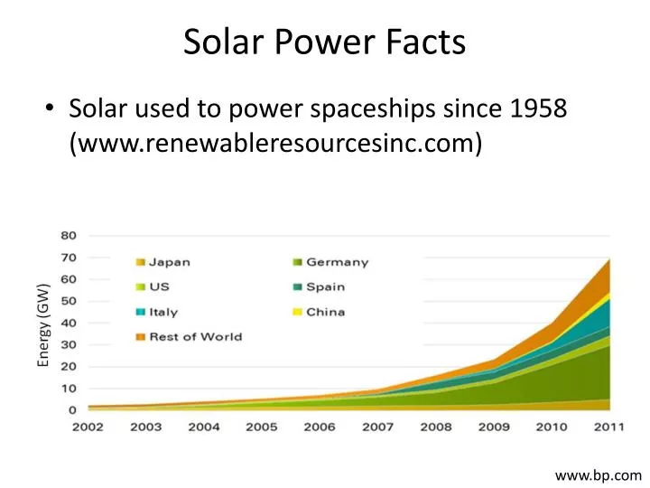
Solar Power Facts. Solar used to power spaceships since 1958 (www.renewableresourcesinc.com). www.bp.com. Photovoltaics. Photoelectric Effect Some materials release electrons when struck by light Photoelectric Cell Two semiconductor wafers (e.g., Silicon)

E N D
Solar Power Facts • Solar used to power spaceships since 1958 (www.renewableresourcesinc.com) www.bp.com
Photovoltaics • Photoelectric Effect • Some materials release electrons when struck by light • Photoelectric Cell • Two semiconductor wafers (e.g., Silicon) • One doped to have free electrons (e.g., Phosphor) • One doped to have shortage of free electrons,“holes” (e.g., Boron) • Photons strike free electrons, giving them enough energy to break free • Photoelectric Modules • Cells added in Series & Parallel to produce particular potential & current www.supplierlist.com
Photovoltaic Jansson
PV Array Cell Module
Electricity Basics • Potential (Voltage) • Current (Amperage) • Direct • Alternating • Resistance (Ohms)
Electricity vs Water • Electricity • Voltage, V • Potential, Volts, V • Current, I • Flow of Electrons, Amperes, Amp, A • Resistance, R • Resistance to flow, Ohms, • Small wire, resister • Water
Power, Direct Current: P = VI • Power, P = Work per unit time, Watts (W) • 1 Watt = 1 Joule / second = 1 Volt Ampere • 1 joule = 1 newton meter • 1 volt = 1 joule/coulomb • 1 coulomb = 6.24151·1018 electrons • 1 ampere = 1 coulomb per second • Assume a 9 V battery has a capacity of ~600 mA hours (“m” = “1/1000”)If it creates a 60 mA current in a circuit: • Power = V I = 9 V x 60 mA = 540 mW = 0.54 W • It could last 600 mAh / 60 mA = 10 hours under ideal conditions • It could do 19,440 J of work under ideal conditions • 9 V x 600 mAh x (3600 s/h) = 19,440 J • 12,000 to 16,000 J is more realistic • It could lift can of soda (3.3. N) ~5,800 m at ~0.16 m/s under ideal conditions • 0.54 N m s-1 / 3.3 N = 0.16 m/s • 19,440 J / 3.3 N = 5,800 m
PV Module Arrays • Modules combined in series & parallel to provide voltage & current for application • Modules make direct current (DC) • often connected to inverter to create alternating current (AC) • Excess power is
Batteries & PV Panels L - + - + - + L - + • Similarities • In Series: Increase Voltage • In Parallel: Increase Current www.makeitsolar.com
PV Solar Panel IV Curve Connect in Series Connect In Parallel
PV Technologies • Monocrystalline Silicon • Polycrystalline Silicon • Lower efficiency than mono, but cheaper to make • Amorphous Silicon (Thin Film) • Even lower efficiency, but even cheaper • Don’t require direct sunlight • Other • Organo PV • Thin-film Cadmium Telluride • Gallium –arsenide • Multijunction – Two layers of cells, trapping different bandwidths of solar rays
www.homepower.com PV Module Layers (Silicon)
www.greentechmedia.com MoneyEuro/kWp installed (Germany)(Roof Mounted, under 100 kW) $2.80 in Germany versus $5.20 US
i00.i.aliimg.com Inclined Roof PV
www.3s-pv.ch MegaSlate – PV & Roof Combined
i01.i.aliimg.com Flat Roof PV
www.daylightnorfolkcompany.co.uk Ground Mount PV
www.nuffieldscholar.org Ground Mount Tracking PV
sroeco.com 220 W Modules Amorphous
Rating PV • Area efficiency (or Density) • Usable energy produced by a module per unit area. • A module that generates 210 Watts in 15 square feet ans a density of 210 W / 15 ft2 = 14 W/ ft2 • Module efficiency • Conversion of set amount of Sun energy to usable energy. • If module generates 15 W of electricity from 100 Watts of sun energy it is 15 % efficient • Cell efficiency • Same as module efficiency, but for single cell • Useful for tracking advances in cell technology, but does not always translate to module efficiency
Types of PV Systems • Stand-Alone DC • Stand-Alone DC w/ Battery Backup • Stand-Alone AC w/ Battery Backup • Grid Connected AC
www.ohmg.org.uk Grid Connected AC
Site Specific Design engineering.electrical-equipment.org • Array Tilt • Array Azimuth • Shading • Partial shading can have significant negative effect • Array • Part of a module • Source of Shade www.civicsolar.com
Surroundings: Solar Path Finder av.solarpathfinder.com
gorgeousgreenhouse.files.wordpress.com Trace Surroundings Analyze with software www.solarpathfinder.com Click FAQ menu, Select “Software Free Trial Version”
Solar PathFinder Output Unshaded Site (Traced outer edge) Shaded Site (Proper Trace)
www.solartechnologies.co.uk Shade FROM PV
Top View Tilt and Azimuth PV Panel Side View North PV Panel PV Panel L Array Azimuth Array Tilt = A Ground Surface or Flat Roof Array Tilt North W Due South is best (Array Azimuth = 180) Array Tilt latitude is best for all year fixed angle Flatter better in summer Steeper better in winter (Ignoring cloud seasonality) When do you need electricity? Is the cost seasonal? Array Azimuth
Imaginary lines that circle earth parallel to equator Location specified by angle between lines from center of earth to equator and latitude www.techdigest.tv Latitude Glassboro ~ 39.8
Fixed Tilt (All Year) • Latitude below 25 • Array Tilt Angle, Aay = 0.87 Lat • Where Lat = Latitude in decimal degrees • Latitude between 25 & 50 • Array Tilt Angle, Aay = 0.76 Lat + 3.1 • Example 1: latitude = 20 • Example 2: latitude = 45 • According to: Macs Lab; Optimum Orientation of Solar Panels; Charles R. Landau; April 2011
Seasonal Array Tilt greenliving.nationalgeographic.com • Winter • Array Tilt Angle, Aw = 0.89 Lat + 24 • Spring and Fall • Array Tilt Angle , Asf = 0.98 Lat – 2.3 • Summer, • Array Tilt Angle , As = 0.92 Lat – 24.3 • Example 3: latitude = 45 • Winter: • Spring and Fall: • Summer :
Array Tilt & Shading • Flat Roof or Ground Applications • Larger the Tilt, farther rows need to be apart to avoid shading each other • ~15 sometimes used to minimize shading & maximize summer production • Panels installed at roof angle on inclined roofs Ground Surface or Flat Roof
Inter-Row Distance(South Facing Array) L h h • dm = h cos / tan • dm = minimum inter-row distance w/ no inter-row shading on winter solstice (Dec 21) between specified hours • = sun altitude angle (alpha) • = sun azimuth (psi) dm A p h = L sin(A), where A = Array Tilt Angle p = L cos(A) solarwiki.ucdavis.edu
Sun Path Chart & • Pick desired shade free period on Dec 21 • 10 AM to 2 PM • 9 PM to 3 PM • Use Univ. of Oregon online program to obtain Sun Path Chart • solardat.uoregon.edu/SunChartProgram.php • Enter zip code (step 1), specify time zone (step 2), select file format (step 6), enter Verification code (step 7) and click “Create Chart” Button
Sun Chart – Pitman NJ = 14 Example 4 on next slide = 180 – 138 = 42 = 220 – 180 = 42
Example 4: Pitman NJ • Let • Location = Pitman, NJ • h = 0.7 m • No shade desired on Dec. 21 from 9 AM to 3 PM • From Sun Path Chart • = • = • dm = h cos / tan = 0.7·cos42 / tan14 • =
PVWatts™ Grid Data Calculator (Version 2)(www.nrel.gov/rredc/pvwatts/grid.html) Enter Zipcode
DC Rating: Module W rating x # of Modules DC to AC Derate Factor: Efficiency producing AC Array Type: Fixed, one axis, two axis Array Tilt: Angle from ground Array Azimuth: Direction from N
Derate Factors for AC Power Rating at STC We won’t change any of these
www.nrel.gov Fixed versus Tracking Arrays We will stick to the “fixed tilt” option
Example 5: Energy / Area • Sharp ND-200 U1 • Poly-Crystalline • 1.6 m x 1 m • L = 1.6 m, W = 1 m • 200W per panel • Open Circuit Voltage = 35.5 V • Short Circuit Current = 7.82 A • Module Efficiency = 12.3 % • Fixed Tilt System on flat roof • Try two Tilt Angles • Aay • 15 • Use Pitman Sun Data • = 14 & = 42 • Roof is 10 m wide in East/West direction • Electricity is $0.1/kWh
Example 5 • How many panels does a “4 kW” system need? • Optimum All Year Array Tilt, Aay = • h = • dm = h cos / tan = • = • ( & from previous example)
Example 5 • Use PVWatt 2 to estimate the annual kWh & Savings from the Array • 4791 kWh • $479
Example 5 • What if you reduced the Array Tilt Angle to 15? • h = • dm = h cos / tan = • = • Use PVWatt 2 to estimate the annual kWh & Savings from the Array • 4761 kWh • $461
Example 5 • Plan Area of Array, Ap = (N W) (R p + (R-1) dm) • N = Number of panels per row • R = Number of rows • Equation works for any N and R N W p dm R p + (R-1) dm
Example 5 • Determine the Array Area for each Title Angle • 20 panels, each with W = 1 m; 10 m wide Roof • Array Tilt = 39.71 • Ap = • Array Tilt = 15 • Ap=
Example 5 • Does the tilt angle effect the Energy produced per Array Area? • Array Tilt = 39.71 • Array Tilt = 15