Download
1 / 5
50 likes | 163 Views
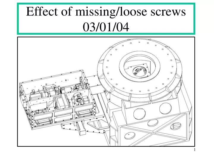
Effect of missing/loose screws 03/01/04. Moment Load about E-W Axis-1. W into page. Base Plate. XY Stage. Box. S. N. 20 lbs +/-5%. George. Brace 2 Plcs. AO-Spool. Result of 20 lbs load: .005 inch flexure at point of application of load. Pivot Point. E.

E N D
Moment Load about E-W Axis-1 W into page Base Plate XY Stage Box S N 20 lbs +/-5% George Brace 2 Plcs AO-Spool Result of 20 lbs load: .005 inch flexure at point of application of load Pivot Point E
Moment Load about E-W Axis-2 • Results: • Applied force tends to rotate Structure about pivot point marked in sketch (prev. slide) • .005 inch Flexure seen will have contributions from Box , XY stage and George Mount • Any looseness in XY stage will contribute to flexure measured • We see .0025 inch by pushing/pulling just on XY stage in E-W direction (Stage Stop?) • Results Interpretation and Suggestions: • Do a flexure test around E-W axis ( going North and South) • .005 flexure translates into an angle at POM of ~ 36arc-sec • Using Zemax, what does a 36 arc-sec tilt at the POM mean? (Doug) • Examine XY stage for looseness (anti-backlash) • Add Braces to George Mount.(see previous slide) • Comments: • Adding Braces to the George Mount means connecting the George Mount to the AO-Spool with tubular material on two sides (see slide). This will stiffen up the George Mount if it is not stiff enough in this plane. It could be tried out by just clamping these rectangular tubes in place and if found to reduce the flexure substantially, permanently bolted to both the AO Spool and the George Mount. We could also rebuild the George Mount, but choose Steel for the Material instead of Alu 6061. • But the preference would be to add the tubular stiffeners, since the XY stage is made from Aluminum 6061-T6, to avoid thermal mismatch between George and XY stage.
Moment Load about parallel to optical axis-1 W into page XY Stage Box S N George 2nd Pt of Application of 20 lbs force Push/Pull 1nd Pt of Application, on George Push/Pull Rot- Axis Optical Axis E
Moment Load about parallel to optical axis-2 • Results: • For 1st Pt of appl.: 20 lbs force: .0005 inch both directions (F on George);see FEA-1 • For 2nd Pt of appl.: 20 lbs force; .0025 inch both directions (F on Box);see FEA-2 • Results Interpretation: • The lever arm ratio between 1st and 2nd Pt of application of the force is about 2:1 with respect to the rotation axis. Treating the structure as a cantilevered arm, the deflection is proportional to the cube of the distance from pivot. We would therefore expect a deflection of (2)^3, or 8 * .0005=.004. We measured .0025, somewhat less, which may be because we have unequal moments of inertia in the structures involved or our measurements reading was .0003 rather than .0005 inch. • We also pushed/pulled on the XY stage in a N-S direction and observed a movement of .0025/.003. This would indicate looseness in the XY stage; could be a problem with the anti-backlash • Suggestions: • Contact XY stage Vendor for info on impact on specs for temperature changes (see site) http://www.neat.com/techinfo/thermal.asp • Using Zemax, evaluate a rotation of 18 arc-sec at location of POM • Disassemble Acquisition Camera; inspect all optical mounts, including POM, for any looseness in the optical mounts; check all bolts; check POM assembly for any looseness • Add missing fasteners to Acquisition assembly (I noticed some are missing) George,Lars