Download

1 / 14
140 likes | 337 Views
Low-Power SRAM Using 0.6 um Technology. Andrew Ashworth Jonathan Chen Matt Williams. Introduction. Metrics: Power(mW), Delay(ns), Area(mm 2 ) Low Power SRAM: (total power) 2 * delay * area SRAM size of 1 Mb Word size of 32 bits One read or one write access per cycle. CLK. CLK1. CLK2.

E N D
Low-Power SRAM Using0.6 um Technology Andrew Ashworth Jonathan Chen Matt Williams
Introduction • Metrics: Power(mW), Delay(ns), Area(mm2) • Low Power SRAM: (total power)2 * delay * area • SRAM size of 1 Mb • Word size of 32 bits • One read or one write access per cycle
CLK CLK1 CLK2 Clock • Two-phase non-overlapping clock generator
<0:3> Word-line Enable Bit 0 1 3 2 <4:7> 4 5 7 6 <8:11> 8 9 11 10 <12:15> 12 13 15 14 A14A13A12A11A10 5:32 <16:19> 16 17 19 18 <20:23> 20 21 23 22 <24:27> 24 25 27 26 <28:31> 28 29 31 30 Array Architecture • Block Selector, Transmission Gates, and Positive Edge Triggered Register
Local WL Local WL Local BLB Local BL Transistors use 0.5 um technology. Sizes shown represent widths of devices. 4.5um To local word-line 1.5um 1.5um 4 1 A5A4A3A2 4:16 4:16 1.5um Enable bit from 5:32 Decoder Enable bit 4.5um 4 4 Enable bit 1 1 A9A8A7A6 4:16 4:16 Numbers shown by inverters are ratios relative to minimum sized inverter Block Architecture • Hierarchical word line with divided bit line
Global Bit-Line Global Bit-Line Bar from Figure 5 Block Architecture Continued Divided bit line approach with 16 bit cells per local bit line
Drowsy Cache • An extra 6t bit cell holds whether block is asleep or awake and selects corresponding Vdd • Requires extra dc-dc converters on chip
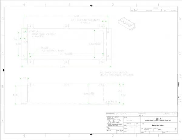
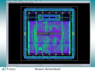
Layout • Horizontal bit cell to maintain square block • We should have learned SKILL
Challenges • Drivers • Clock generation – iterated through 3 designs before finally settling on a pulsed NOR design. • Designing sense amp enable driver
Simulation • Extracted parasitic capacitances from layout to build accurate array model • Simulated model of one block to represent entire array • Began with worst case 50C and SS to find stable clock
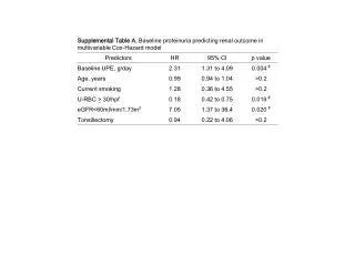
Results • The SRAM correctly performed a write followed by a read at all process corners, and temperatures • As VDD is scaled down, leakage power decreases by orders of magnitude. We have no reliable numbers as power simulations returned unrealistic results for 5V VDD
Metric • Total Size: about 500mm^2 • Average Power: about 9mW • Delay: about 35ns • Total Metric: 1.458 million