Download
1 / 12
130 likes | 257 Views
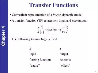
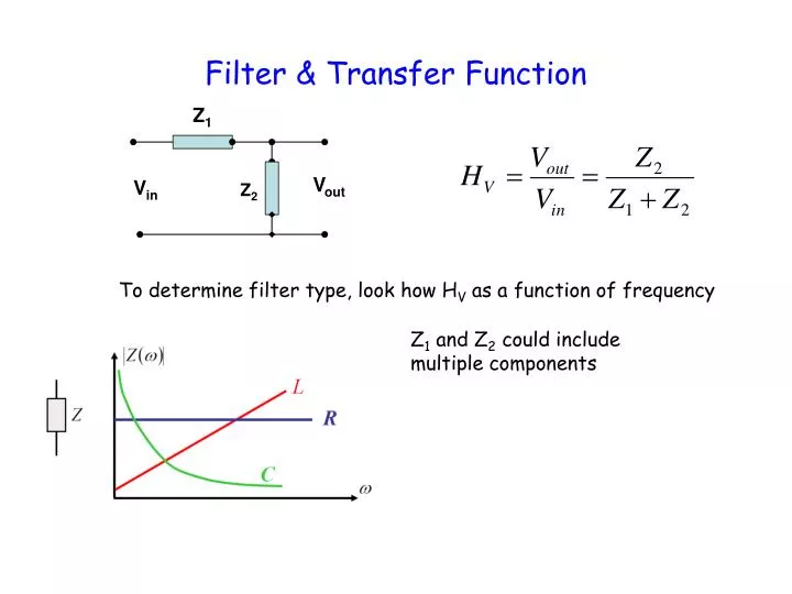
Z 1. V out. V in. Z 2. Filter & Transfer Function. To determine filter type, look how H V as a function of frequency. Z 1 and Z 2 could include multiple components. RLC at Resonance. At resonance: current is max. Z eq =R current and voltage are in phase.

E N D
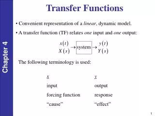
Z1 Vout Vin Z2 Filter & Transfer Function To determine filter type, look how HV as a function of frequency Z1 and Z2 could include multiple components
RLC at Resonance • At resonance: • current is max. • Zeq =R • current and voltage are in phase. • the higher Q, the narrower the resonant peak.
Exam II Review: AC Power Average power rms value • The average ac power (Pav) is the power dissipated on the load resistor. • 0cosq1, dependent on the complex load. • ideal power factor: cosq =1, Z=R, pure resistive load
Complex Power • real power Pav(unit: watts): power absorbed by the load resistance. • reactive power Q (unit: volt-amperes-reactive, VAR): exchange of energy between the source and the reactive part of the load. No net power is gained or lost during the process. Q=QL-QC, if Q<0, the load is capacitive, Q>0, the load is inductive • Apparent power: |S|=|Vrms||Irms| (unit: volt-amperes, VA): computed by measuring the rms load voltage and currents without regard for the phase angle.
Transformer Transformation of Voltage: Transformation of Resistance:
Residential Wiring GFCI
Example: Midterm 1998 An electrical engineering major has designed and constructed a motor for your sophomore design project. It has been wound with an inductance of 16 mH and a resistance of 3.0 ohm. You had specified that it be optimized for the best possible power factor at 60 Hz; consequently, a 354 microFarad capacitor was added in parallel with the motor, as shown below. a. Operated at 120 V, what is the current through the motor when operated at 60 Hz? b. What power is delivered by the voltage source? c. What power is dissipated by the motor? Your complete project was so innovative that your engineering professor entered it in an international competition. You arrive in Germany for the competition before remembering that the line frequency there is 50 Hz. d. What is the power factor of this circuit at 50 Hz? e. What capacitance do you need to replace 354 mF capacitor in order to correct the power factor back to unity?
Example Cont. a. Operated at 120 V, what is the current through the motor when operated at 60 Hz? b. What power is delivered by the voltage source? d. What is the power factor of this circuit at 50 Hz? e. What capacitance do you need to correct the power factor back to unity? Note: you calculate S only on the motor part! Negative just means Capacitor
Example 3: 1st Fall 199 • An electrical engineering firm has designed a motor for your sophomore design project. You specified that it should be wound with an inductance of 16 mH and a resistance of 3.0 ohm. You had specified that it be optimized for the best possible power factor at 60 Hz; consequently, a 354 mF capacitor was added in parallel with the motor. Unfortunately the motor was actually wound with an inductance of 61 mH and a resistance of 30 ohm because of typographical errors in the FAX to the motor manufacturer. • What power is delivered by the voltage source? • What power is dissipated by the motor? • What capacitance do you need to replace 354 mF capacitor in order to correctthe power factor back to unity?
Example Cont. a. What power is delivered by the voltage source? b. What power is dissipated by the motor? d. What capacitance do you need to correct the power factor back to unity?