Download
1 / 9
90 likes | 229 Views
Supported by. XP728: RWM active stabilization and optimization – ITER scenario. Columbia U Comp-X General Atomics INEL Johns Hopkins U LANL LLNL Lodestar MIT Nova Photonics NYU ORNL PPPL PSI SNL UC Davis UC Irvine UCLA UCSD U Maryland U New Mexico U Rochester U Washington

E N D
Supported by XP728: RWM active stabilization and optimization – ITER scenario Columbia U Comp-X General Atomics INEL Johns Hopkins U LANL LLNL Lodestar MIT Nova Photonics NYU ORNL PPPL PSI SNL UC Davis UC Irvine UCLA UCSD U Maryland U New Mexico U Rochester U Washington U Wisconsin Culham Sci Ctr Hiroshima U HIST Kyushu Tokai U Niigata U Tsukuba U U Tokyo JAERI Ioffe Inst TRINITI KBSI KAIST ENEA, Frascati CEA, Cadarache IPP, Jülich IPP, Garching U Quebec S.A. Sabbagh1, R.E. Bell2, J.E. Menard2, D.A. Gates2, J.M. Bialek1, B. LeBlanc2, F. Levinton3, K. Tritz4, H. Yu3 1Department of Applied Physics, Columbia University, New York, NY 2Plasma Physics Laboratory, Princeton University, Princeton, NJ, USA 3Nova Photonics, Inc., Princeton, NJ, USA 4Johns Hopkins University, Baltimore, MD, USA NSTX Team XP Review Meeting May 8th, 2007 Princeton Plasma Physics Laboratory V1.1
XP728: RWM active stabilization and optimization • Goals • Investigate variations of control sensor combinations to optimize RWM stabilization at low plasma rotation, wf (more robust, reach higher bN) • Use upper/lower RWM Br, Bp sensors for feedback (ran out of time in 2006) • Examine possible poloidal deformation of RWM during feedback • Investigate active stabilization of recent plasmas that exhibit unstable RWM activity leading to discharge termination at highwf. • Explore possible stable region at wf < w*i with feedback is turned off • Investigate RWM active stabilization of low wf plasma with superposed time-averaged n = 1 error field correction + n = 3 magnetic braking • (Fredrickson, Garofalo suggestion from 2006, but no run time) • Measure n =2-3 RFA, attempt to destabilize n = 2 RWM with n = 1 stable • Introduce and study effect of applied time delay on feedback (ITER support) • Depends on control system time delay capability in 2007 • Addresses • NSTX milestone R(07-2), NSTX PAC request • ITPA experiment MDC-2, ITER issue card RWM-1, USBPO MHD task
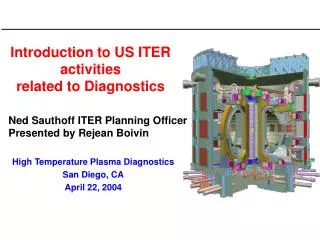
no-wall bN > bN (n=1) 0.4 0.5 0.6 0.7 0.8 0.9 t(s) RWM actively stabilized at low, ITER-relevant rotation 92 x (1/gRWM ) Control ON 6 • Logical next-step of XP615 addresses several key issues • Optimal RWM sensor configuration • Dependence of active stabilization on wf • Possible stable region at sufficiently lowwf without active stabilization • If stable region with low wf is found, scan magnitude to determine range of stable wf. • Approach • Follow established Xp615 procedure to generate RWM stabilized, low rotation target • Make control system parameters scans, rotation scans to fulfill stated goals 120047 4 bN 2 Control OFF 0 120712 8 wf < Wcrit 4 wf/2p (kHz) 0 1.5 IA (kA) 1.0 0.5 0.0 DBpun=1 (G) 20 10 0 20 DBpun=2 (G) 10 0 (Sabbagh, et al., PRL 97 (2006) 045004.)
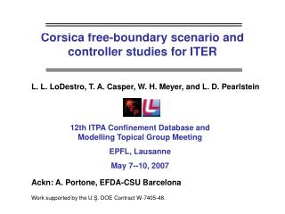
6 bN collapse 4 bN 2 0 4 2 wf/2p(kHz) 0 DBpu,ln=1 (G) 20 10 0 DBru,ln=1 (G) 8 4 0 DBr extn=1 (G) 6 4 bulge 2 120048 0 0.55 0.59 0.63 0.67 0.71 0.75 t (s) Test improved control with addition of new sensors • Poloidal deformation of RWM sometimes observed • Poloidal n = 1 RWM field decreases to near zero; radial field increasing • Subsequent growth of poloidal RWM field • Asymmetric above/below midplane • Radial sensors show RWM bulging at midplane • midplane signal increases, upper/lower signals decrease • Theory: may be due to other stable ideal n = 1 modes becoming less stable • Approach • Include full set of RWM sensors (upper and lower, Bp and Br) in feedback circuit – new PCS capability (tested piggyback 2006) wf ~ Wcrit upper lower
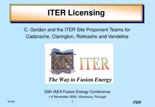
Does stable high bN, low wf region exist without feedback in NSTX? • Non-resonant n = 3 magnetic braking used to slow profile • The wf/wA < 0.01|q = 2 • The wf/Wcrit = 0.2|q = 2 • The wf/Wcrit = 0.3|axis • Less than ½ of ITER Advanced Scenario 4 wf/Wcrit (Liu, et al., NF 45 (2005) 1131.) • Possible energy dissipation at low rotation speeds • trapped particle precession drift stabilization at wf < w*i(Betti and Hu, PRL 93 (2004) 105002.) • Approach • Generate bN > bNno-wall (n = 1) actively stabilized plasma at low wf magnitude • Gate feedback off/on to probe low rotation stable operating regime (seen in DIII-D – Reimerdes, et al. PRL 98 (2007) 055001.) passively stabilized by rotation (120038, t = 0.535s) wf/wA experimental critical rotation profile Wcrit/wA (120712, t = 0.575s) (axis) actively stabilized (120047 t = 0.825s) (q=2) } (120717, t = 0.915s) R (m)
Control ON (fast bN drop, plasma recovers) 40 n = 2 internal mode negative feedback response (kHz) 40 n = 1 DBpu (G) 20 n = 2 20 n = 2 n = 1 0 0 0.6 0.8 t(s) 0.66 0.70 0.74 0.78 t(s) 1.5 edge 120717 1.0 USXR (arb) 0.5 20 ms core 0.0 0.7239 0.7240 0.7241 0.7242 t(s) n = 2 RWM does not become unstable during n = 1 stabilization • …but, can the n = 2 RWM be driven unstable at higher bN? • Unstable n = 1 – 3 RWMs already observed in NSTX (Sabbagh, et al., NF 46 (2006) 635.) • Generate controlled, measured n = 2 RFA during n = 1 stabilization, and drive unstable • Approach • RFA measurements for n = 2 and 3 can be made for most conditions • To destabilize n = 2 RWM, use “optimized” control system configuration and plasma configuration to maximize bN • Internal mode ~ 25 kHz (n=2)
XP728: Active RWM Stabilization - Run plan (Part 1) Task Number of Shots 1) Create target plasma A) Run active feedback in piggyback mode in prior experiments to verify operation - B) 3 NBI, k > 2.2, bN > bNno-wall (control shot - 123529 as setup shot) 1 C) Drop Ip to 0.9 MA from 1.0 MA 1 2) Reproduce active RWM stabilization at low plasma rotation A) n = 3 braking, n = 1 feedback w/Bpu sensors, adjust n = 3 braking if wf > 0.5 Wcrit 2 B) Reproduce (2A) with n = 1 feedback off - demonstrate unstable RWM at low wf 2 3) Optimize n = 1 feedback sensors at low wf A) Adjust relative phase between sensors / RWM coil current if (2A) <> shot 120717 3 B) Add Bpl sensors to feedback circuit 1 C) Use Bpu + Bpl average (150 degree spatial offset) 1 F) Vary relative phase between sensors / RWM coil 4 D) Add upper/lower Br sensors to feedback circuit 1 E) Add Bru + Brl average (260 degree spatial offset) 2 G) Vary relative phase / feedback parameters to further optimize performance 6 __________________________________________________________ Total: 24
XP728: Active RWM Stabilization - Run plan (Part 2) Task Number of Shots 4) n = 1 RWM stabilization with various rotation profiles < Wcrit (best feedback settings from step (3)) A) Vary n = 3 braking current to create scan of profiles 0 < wf << Wcrit 8 Gate off active feedback for many wall times (100 ms) to determine which, if any profiles are stable at low rotation without n = 1 feedback B) If any wf profiles are stable without n = 1 feedback in (5A), re-run shot with 2 feedback turned off 5) Check pre-programmed average of n = 1 feedback current for stabilization A) Attempt stabilization using avg. n = 1 feedback current for best case of (3) above 2 B) If successful, vary plasma parameter(s) (e.g. k) to test robustness of stabilization 2 6) Measure n > 1 RFA at maximum bN; attempt n = 2 RWM destabilization with n = 1 stable A) Take highest bN stabilized plasma at low and run at maximum bN/bNno-wall (options: increase NBI power, optimize DRSEP, use lithium, drop Ip by 100A) 2 7) Examine feedback performance vs. feedback system latency A) Increase feedback system latency from optimized settings to find critical latency for mode stabilization 6 __________________________________________________ Total: 16 w/o latency scan; 22 with latency scan
XP728: Active RWM stabilization - Diagnostics • Required diagnostics • Internal RWM sensors • CHERS toroidal rotation measurement • Thomson scattering (30 point) • USXR • MSE • Toroidal Mirnov array / between-shots spectrogram with toroidal mode number analysis • Diamagnetic loop • Desired diagnostics • FIReTip • Fast camera