Download
1 / 29
300 likes | 536 Views
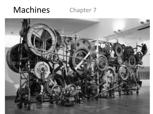
Machines. All Machines. When we first think of machines we tend to think of things such as cars, bulldozers or computers. A machine does not reduce the amount of work to be done, but it reduces the human labour by transferring energy from one place to another.

E N D
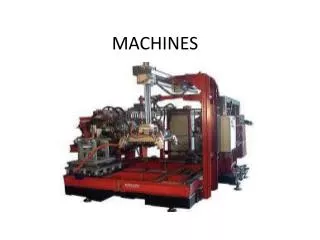
All Machines • When we first think of machines we tend to think of things such as cars, bulldozers or computers. • A machine does not reduce the amount of work to be done, but it reduces the human labour by transferring energy from one place to another. • These are known as complex machines and are made up of a combination of 5 basic types of simple machines…
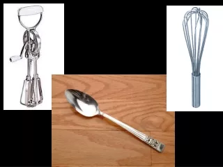
All Machines From hammers to can openers they make physical tasks easier. Simple Machines • Levers • Inclined plains • Wheel and axles • Pulleys • Gears Complex Machines • Combinations of levers, gears, wheels, pulleys.
Simple Machines • Machines can magnify a force. • Example: a crow bar can be used to lift a rock. • Machines can help us by changing the direction of a force. • Example: raising the sails on a boat with a pulley. • Machines can make things go faster. • Example: turning the handles on an egg beater makes the beaters go faster. • In a simple machine, if the effort applied is less than the load then the machine has a force advantage. • In a simple machine, if the effort is greater than the load, the simple machine has distance advantage. • Let’s have a look at this in terms of levers…
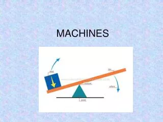
Levers • Levers can be used for many different purposes in our every day lives. • A lever is a rigid bar that can turn around a pivot point known as a fulcrum. • Examples include the human forearm, a fishing rod, a seesaw, tweezers, crowbar, nutcrackers, scissors and pliers. • There are 3 types and they are known as first, second and third class levers…
Levers – 1st Class • A first class lever is like a seesaw. The point of pivot at the fulcrum is in the middle with the load at one end and the effort at the other. • Other examples include crowbars and balance scales. • If the effort and load have equal mass and their length from the fulcrum is equal, they will balance. • If the effort has a greater mass to the load, it needs to be closer to the fulcrum in order for them to balance. • First class levers are used for lifting. They are known as force multipliers because they convert a small force into a bigger one. http://www.ent.ohiou.edu/~bobw/html/HapEd/NASA/SimpMach/Lever.htm
Levers – 2nd Class • A second class lever lifts like a wheelbarrow. The wheels axle is the fulcrum, the effort is applied at the handles and the load sits in the middle. • The load is between the fulcrum and effort. This means the distance moved by the load will always be less than the distance moved by the effort. This means these leavers are useful for lifting heavy loads. • Second class levers are also known as force multipliers. http://www.ent.ohiou.edu/~bobw/html/HapEd/NASA/SimpMach/Lever.htm
Levers – 3rd Class • A third class lever could be called the sportsman's lever. Racquet sports such as tennis, badminton, and fishing require the use of a rod shaped tool. The fulcrum is at the wrist and the effort force is throughout the length of the rod and the load is on the very end. • Because the effort is between the fulcrum and the load, the distance moved by the load will always be more than the effort. These levers are therefore used for moving rather than lifting. • Third class levers are known as distance multipliers because they convert a small movement into a bigger movement. http://www.ent.ohiou.edu/~bobw/html/HapEd/NASA/SimpMach/Lever.htm
Levers – which class? • An easy way to remember the 3 classes is to simply say… FLE 123
Which class levers are these? E F Effort in the middle = 3rd class L Load in the middle = 2nd class F E Fulcrum in the middle = 1st class L F L Effort in the middle = 3rd class http://www.connect.ab.ca/~lburns/students_eightunit2notes.html
Which class levers are these? F L E E Load in the middle = 2nd class Fulcrum in the middle = 1st class Effort in the middle = 3rd class Load in the middle = 2nd class F F L E http://www.connect.ab.ca/~lburns/students_eightunit2notes.html
Inclined Planes It is easier to drag a heavy object up an inclined plane than… • An inclined plane is a sloping surface which can be used to raise a load by moving it up the slope. • The less steep the slope, the more the inclined plane supports the load…although, the longer the slope becomes in order to lift to a certain height! • There are two special types of inclined planes, they are the wedge and the screw… …lift it vertically
Inclined Planes – the wedge • A wedge is a double sided inclined plane and includes items such as chisels, axes and knives. • Wedges can be used to split or cut other objects. • The amount of friction created by using a wedge to cut can be reduced by making the blade as thin and sharp as possible.
Inclined Planes – the screw Pitch Thread • The screw is an inclined plane wrapped around a central cylinder. • Even though you have to turn a screw many times, it requires a smaller effort than driving it directly into the wood. • The smaller the pitch, the greater the advantage. • A screw is like a second class lever. The fulcrum is at the screws point, the load is where the thread touches the material, and the effort is where the screwdriver touches the head of the screw.
Pulley Systems – Single pulley • A pulley is a wheel that turns on an axis and has a grooved rim for a belt or a rope. • Examples include: cranes, flagpoles, elevators and sewing machines. • A single fixed pulley is similar to a first class lever. Where is the fulcrum? • A single pulley does not provide a force or distance advantage but can be useful because they change the direction of the effort needed to lift or move a load. • With one pulley the load seems lighter because the effort works with gravity rather than against it, that is the effort pulls down rather than pushes up. http://www.micron.com/k12/lessonplans/machines/pulleys.html
Pulley Systems – what they can do • They change the position of a rotating movement • Change the direction of rotation • Increase or decrease the speed of rotation • Increase the turning force • Change direction of a pulling force • Increase a pulling force
Pulley Systems – Double pulley • Two pulleys can be connected by a belt. When one pulley is turned, the belt causes the other pulley to turn as well. A car engine uses a belt to drive turn pulleys on other devices such as a water pump or an air conditioner. • More than one pulley reduces the effort required to lift a load. The payoff for this is that you have to spend a longer amount of time lifting the load. http://www.micron.com/k12/lessonplans/machines/pulleys.html
Pulley Systems – Block and Tackle • The block and tackle is a system of pulleys that is compact, but is able to raise large loads because it has so many wheels. The force of a block and tackle is multiplied by each pulley wheel it contains. • Pulley blocks provide large force advantages. • The block and tackle in the diagram contains five pulleys in each set plus a guide wheel above. The load is raised by ten pulleys, so the block and tackle increases the force applied to it ten times. • Using a block and tackle with ten pulleys, you could lift a mammoth weighing up to 600 pounds! What is the payoff for this? http://www.micron.com/k12/lessonplans/machines/pulleys.html
Wheels and Axles • The idea of the wheel has been around for thousands of years but it is not known where it actually originated from. • A wheel and axle is like a pulley, but has the wheel firmly fixed to the axle so that both turn together. The axle is really a smaller sized second wheel. • A wheel is defined as a solid disc or as a circular ring with spikes, designed to turn around a smaller axle (a rod) passing through its center. • The wheel and axle can control the direction of the movement. • Increases the turning force – applying a small force to turn the larger wheel (such as in a winch) produces a larger force to turn the smaller axle.
Gears • A gear is a set of toothed wheels (gear wheel or cog-wheel) that work together to transmit movement. • A gear wheel functions by using its teeth to turn another gear wheel in the opposite direction. In order for one gear wheel to turn another, the two must be placed next to each other so that the teeth mesh or engage each other. As one gear wheel is turned, its teeth push on the teeth of the adjacent gear wheel, forcing it to turn as well. The follower gear wheel is turned by another gear wheel The driver gear wheel is the one turned by an outside force
Gears • Gears can change the position of a rotating movement. • Gears can change the direction of a rotation. • Gears can increase or decrease the speed of rotation. • Gears can increase the turning force. • A pawl is a block or a wedge that drops between the teeth of a gear wheel to prevent it from rotating. • A ratchet is a gear wheel used with a pawl. • The gear ratio can be used to compare how two meshed gear wheels move relative to each other… www.jjcassociates.com/ gears/index.shtml
Gears Ratios Gearing Up • When the driver wheel is larger than the follower wheel. • This results in a speeding up of the turning. • Gear ratio can be calculated by dividing the number of teeth in the follower wheel by the number of teeth in the driver wheel. # follower teeth Gear ratio = # driver teeth 8 follower teeth Gear ratio = = 1:5 40 driver teeth
Gears Gearing Down • When the driver wheel is smaller than the follower wheel. • This results in the slowing down of the turning. • Gear ratio can be calculated by dividing the number of teeth in the follower wheel by the number of teeth in the driver wheel. # follower teeth Gear ratio = # driver teeth # 40 teeth Gear ratio = = 5:1 # 8 teeth
A E F G B C D Gears If wheel A is the driver gear and turned in an anti-clockwise direction, in which direction will wheel G turn? Order the gear wheels from fastest turning to the slowest turning. B/D/F, E/A/C, G
Machine Efficiency • The efficiency of a machine can be calculated by working out the ratio of the work output of a machine to the work input. Work done by machine Efficiency = Work done on machine • Example: If 500J of work is done on a pulley block, it does 200J of work in moving a load? 200 Efficiency = = 2/5 500
Mechanical Advantage • The mechanical advantage of a machine is the ratio of its output force, which is the load, divided by its input force which is the effort. Load MA = Effort • What is the mechanical advantage of a car jack which needs an effort of 200N to lift a load of 1200N? 1200 MA = = 6 200
Work The work done by a machine can be described as the force applied through a distance. This can be calculated using a simple formula. Work (J) = force (N) x distance (m) If a man pushes a box with a force of 0.3kg which causes it to move a distance of 2m, how much work has he done? (Note: 1kg = 10N) Work = 3 x 2 Work = 6 J
The End Good luck building your own machines!