Download
1 / 20
490 likes | 972 Views
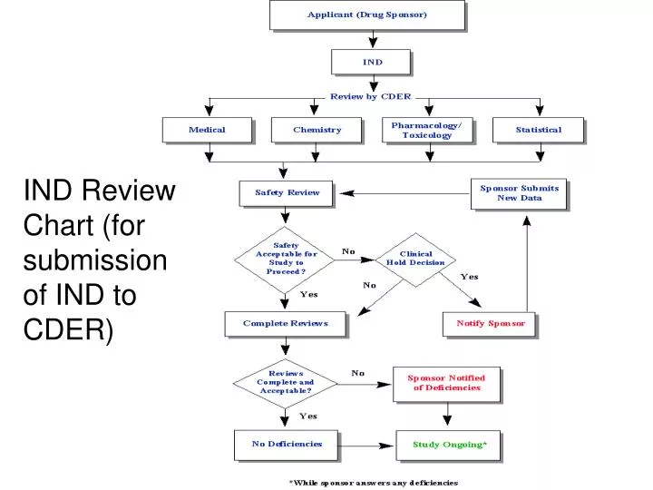
IND Review Chart (for submission of IND to CDER). NDA Review Chart (for submission to CDER). A Warning Letter. Picture of a Clean Room. Incoming air supply. Ceiling. HEPA filter. Diagram of the Flow Pattern of HEPA-Filtered Air Through a Typical Clean Room. Exhaust unit.

E N D
Incoming air supply Ceiling HEPA filter Diagram of the Flow Pattern of HEPA-Filtered Air Through a Typical Clean Room Exhaust unit Items of clean room equipment
Clean Room Classification How clean rooms are classified: Two standards are used to classify clean rooms. The first, Federal Standard 209E, is used domestically and the newer standard is TC 209 from the International Standards Organization (ISO). Both standards classify a clean room by the number of particles found in the laboratory’s air. If a laboratory is a class 10 clean room by the Federal Standards, there are less than 10 particles per cubic foot. The following chart relates FS to ISO classifications and recommended action levels of microbiological quality, i.e. the maximum levels in the clean room air that microorganisms should be allowed to reach:
aParticles are of size 0.5 μm; the standard varies for particles of different sizes. bcfu means colony forming units. c Samples from Class 100 (ISO 5) environments should normally yield no microbiological contaminants.
Transfer lock door Transfer lock Generalized Clean Room Design Clean room Entry of raw material Entry of personnel (changing room) Transfer lock Bench Exit of personnel (changing room) Exit of product
A Peristaltic Pump Principle of operation Fluid Rotor Flexible Tubing
On/Off valve Steam (in) Steam (out) Water (in) Water (out) • Diagram of a typical jacketed processing vessel • Such vessels are usually made from high grade stainless steel • By opening or closing the appropriate valves, steam or cold water can be circulated • through the jacket • In this way the vessels contents can be heated or cooled, as appropriate • In addition, passage of steam through the jacket of the empty vessel will effectively • sanitize its internal surfaces
The range of CIP agents most often used to clean/sanitize chromatographic columns 0.5-2.0 M NaCl Non-ionic detergents (0.1-1.0%) NaOH (0.1-1.0 M) Acetic acid (20-50%) Ethanol (~20%) EDTA (~1.0 mM) Protease solution Dilute buffer Most CIP protocols would make use of two or more of these agents, allowing them to percolate sequentially through the column at a slow flow rate. Contact time can range from several minutes to overnight. Sodium hydroxide (NaOH) is particularly effective at removing most contaminant types.
Sterilization-in- Place Module
Bulk Freeze-Thawing of Purified Protein Preparation & Posidyne- Filtration of Required Buffers Formulation Process (Addition of Necessary Buffers, Purified (Thawed) Protein, and other Ingredients) Filtration of Formulated Material through a 0.22 micron Filter Schematic of Formulation-Fill Unit Operation Sequence Filling of Vials (The unit operation train will be different for a sustained-delivery formulation or a formulation that requires the use of a delivery device)