Download

1 / 55
560 likes | 584 Views
MAXIGAS (Level 1 ) Service Training. MAXIGAS Nitrogen Generator. January 5, 2020. 1). Product Overview: a). What is it’s function. b). Principles of operation. c). Specification & available models. d). Identification labels. e). Product layout & interfaces.

E N D
MAXIGAS (Level 1 ) Service Training. MAXIGAS Nitrogen Generator January 5, 2020
1). Product Overview: a). What is it’s function. b). Principles of operation. c). Specification & available models. d). Identification labels. e). Product layout & interfaces. f). Recommended storage requirements. 2). Installation & Operation: a). Location requirements. b). Mechanical Installation. c). Electrical Installation. d). System start up. e). System operation animations. f). System shutdown. g). Commissioning and warranty passport. Section headings:
Section headings (Continued): • 3). Modes of Operation: • a). O2 Alarm. • b). Low air inlet pressure alarm. • c). Economy mode. • d). Optional inputs / outputs. • 4). Routine Maintenance: • a). PM Schedule. • b). PM Kits. • c). PM Procedures. • d). Oxygen Analyzer calibration. • 5). User Guide: • 6). Modbus Manual: • 7). Questions:
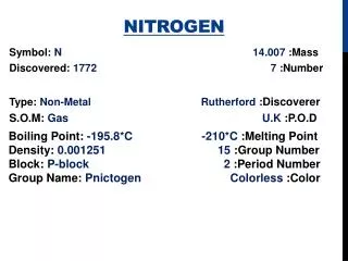
1a). What is it’s function: The function of the MAXIGAS Nitrogen generator is to produce Nitrogen gas at varying purities, flows and delivery pressures to meet the end customers specific needs in line with his production process. The process by which it achieves this, is called the Pressure Swing Adsorption (PSA) principle which produces a continuous stream of nitrogen gas from clean dry, particulate free compressed air.
1b). Principles of operation: The main body assembly of the MAXIGAS Nitrogen generator is made up of pairs of dual chamber extruded aluminium columns, filled with Carbon Molecular Sieve (CMS), which are linked via an upper and lower manifold to form a two bed system made up of “Column A”, left hand side and “Column B”, right hand side. Clean dry compressed air enters the bottom manifold and flows up through the CMS in “Column A” where upon Oxygen and other trace gases are preferentially absorbed / separated with the Nitrogen passing through. Meanwhile, “Column B” is offline in the regeneration phase, where upon all of the contaminants preferentially absorbed / separated by the CMS during the “online” phase are vented from the CMS via the exhaust cylinder / silencer. To aid this regeneration phase, a small flow of the Nitrogen outlet gas from the “online” column is expanded into the bed via the purge valves at the top of the columns to accelerate the regeneration process.
Principles of operation (Continued): The lower purity (%) generators use an equalisation phase designed to reduce energy consumption and enhance the overall performance of the generator. Immediately after the “online” phase the inlet, outlet and exhaust cylinders close on both columns and then the upper and lower equalisation valves open, allowing the pressure to equalise between the columns. The column entering the “online” phase is pressurised by using both a controlled flow of Nitrogen gas from the nitrogen buffer vessel (Back Fill) and a controlled flow of clean, dry, particulate free compressed air (Front Fill). The higher purity (ppm) generators do not have an equalisation phase so a Non-return valve must be fitted after the N2 to buffer ball valve to prevent back fill from the buffer vessel which will affect outlet flow, pressure and purity. Please see next slide for PSA system operation ...........
Principles of operation (Continued): The CMS beds alternate between “online” and “offline” phases to ensure continuous and uninterrupted nitrogen production. The Oxygen concentration in the nitrogen stream is analysed continuously by an internal O2 Analyzer. If the Oxygen concentration exceeds the required production target alarm level, a signal is sent by the O2 analyzer to the control board, which closes the Nitrogen outlet cut solenoid valve, preventing bad gas going to the process and opens the Excess O2 vent solenoid valve to vent the bad gas to atmosphere. During this self clean process the generator will cycle normally. Normal operation will resume automatically when the purity recovers to a level within the alarm settings of the generator.
Specification and available models (Continued): • Air Inlet air quality is important - poor quality air will damage components and CMS. • Recommended air quality is : ISO 8573.1 Class 3.2.2. Dirt, Water Oil (PNEUDRI Midi / Maxi). This ensures : • Optimum generator performance. • The CMS will last the lifetime of the generator (approx. 10 years).
1d). Identification labels: * Connection available on both sides of the generator.
1e). Product Layout & Interfaces (External, LHS): Display Board N2 to Buffer Outlet. Power & Comms. Cable Glands Column “A” Pressure Gauge N2 Outlet Pressure Gauge Column “B” Pressure Gauge Air Inlet Pressure Gauge. N2 from Buffer Inlet. 3 way Ball valve / N2 delivery Outlet. Compressed Air Inlet. Exhaust Silencer
Product Layout & Interfaces (External, RHS continued): Calibration Gas Inlet port Knock out blanking discs for right hand side connection Door handle and Catch
Product layout and interfaces (Internal, Non-Equalizing): Purge valves N2 Outlet Restrictors (Back Fill) N2 Outlet Cylinders Non-return valve Oxygen Analyser Power Supply O2 Cell Control Board Cell Protection Assy. Control Solenoid Valves (6 x Manifold) N2 Outlet Cut / Excess O2 vent solenoid valves manifold assy. Outlet Pressure Regulator N2 Outlet Pressure Switch Mass Flow Controller(s) Air Inlet Cylinders Air Inlet Pressure Switch Air Inlet Restrictors (Front Fill) Exhaust Cylinders
Product layout and interfaces (Internal, Equalizing): Control Solenoid Valves (7 Manifold) Equalization Cylinder (Back Fill) Equalization Cylinder (Front Fill) Kaddis Drain / Ball Valve
Product layout and interfaces (Hi-Pressure, Equalizing): High Pressure Purge Valves Assembly. Outlet Pressure Transducer (0-20 Bar). Air Inlet Pressure Regulator for Control Solenoid Valves Excess O2 vent silencer assy.
1f). Recommended storage requirements: On receipt of the equipment inspect the packing crate for damage. If damaged, remove the top panel of the packing crate and inspect the generator for any external damage. If any external damage is seen inform the delivery company immediately and contact your local domnick hunter office. If the equipment is to be stored prior to installation, do not remove it from the packing crate. Please ensure that it is stored in a suitable location in line with the environmental conditions as specified in the technical specification section in the user guide. Note. It is essential that it be moved to its final location (installation site) and left to stabilise prior to start up. Failure to do this could cause condensing humidity and potential failure of the Equipment.
2a). Location requirements: The generator should be located indoors on a flat surface and protected from direct sunlight, moisture, and dust. Ensure that there is sufficient free space for maintenance access and lifting equipment. DO NOT position the generator so that it is difficult to operate or disconnect. When positioned in its final location, secure the generator to the floor using M20 bolts through the support legs. Due to the nature of operation there is a possibility of oxygen enrichment surrounding the generator. Ensure that the area is adequately ventilated. Where the risk of oxygen enrichment is high, such as a confined space or poorly ventilated room, the use of oxygen monitoring equipment is advisable.
2b). Mechanical Installation: Once the generator has been moved to it’s final location fit the ball valves to the ports on the generator and buffer vessel. All ppm generators are supplied with a non return valve, this should be fitted to the ball valve on the port marked “To Buffer Vessel”. Ensure that all piping materials are suitable for the application, clean and debris free. All outlet piping must be solid and non-porous to minimise the ingress of oxygen. When routing the pipes ensure that they are adequately supported to prevent damage and leaks in the system. The nitrogen buffer vessel must be rated to at least the maximum operating pressure of the generator and must be fitted with suitable pressure gauge and pressure relief valve. It is recommended that the system be protected with suitably rated pressure relief valves upstream of the generator.
2c). Electrical Installation: In order to maintain the IP rating of the generator, all cables entering the electrical enclosure must do so through the dedicated cable glands located on the side of the generator. All cables external to the generator must be adequately supported and protected against physical damage. Please refer to the next slide for the wiring diagram, cable sizes etc ………………….. A fully qualified electrical engineer must undertake all field wiring and electrical work in accordance with local regulations.
Electrical Installation (Continued): Connection to the electrical supply should be made through a switch or circuit breaker rated at 250VAC, 15A with a minimum short circuit rating of 10KA. All of the current carrying conductors should be disconnected by this device. The device chosen should be clearly and indelibly marked as the disconnecting device for the equipment and be located in close proximity to the equipment and within easy reach for the operator.
2d). System startup: Start the dedicated compressor and allow it to build pressure until it goes “offload”. Alternatively, open the air inlet valve from your compressed air ring main and allow the system supply pipe work to pressurise then check all connections / piping for leaks up to the inlet of the pre-treatment dryer. Open the inlet and outlet valves of the pre-treatment dryer and check all connections / piping for leaks up to the air inlet port of the Nitrogen generator. With both the inlet and outlet ball valves of the buffer vessel closed, open the ball valve on the air inlet port to allow the compressed air into the generator, then verify that you have the correct air inlet pressure as stated on the rating plate. Switch the electrical power on to the generator and wait whilst the controller completes it’s initialisation routine. Press [ ] to initiate the start up routine. The generator will now run through the Rapid Cycle (%) or Pure Start (ppm) start up sequence before delivering any gas to buffer vessel.
System startup (Continued): Slightly open the ball valve on the inlet to the buffer vessel and leave it to pressurise slowly Until the pressure gauge on the buffer vessel reads within 0.5 barg (7psig, 0.05MPa) of the generator air inlet pressure before opening the inlet ball valve fully. Check for leaks in the inlet piping and also at all connections points on the buffer vessel. Open the ball valve on the outlet of the buffer vessel and check for leaks in the piping / dust filter from the buffer up to the “N2 from Buffer” inlet at the Nitrogen generator. When all leak tests have been done and no leaks are present then open the N2 outlet 3 way ball valve and start to deliver gas to the end users process. Note: If the purity of the gas is not within specification after a period of 60 seconds it will be vented to atmosphere through the a Excess O2 vent solenoid within the generator and not delivered to the application. When the required purity is achieved the gas will once again be delivered to the application.
2e). System operation animations: The following slide contains a series of Shockwave flash animations designed to illustrate the installation and functionality of components contained in a typical MAXIGAS Nitrogen generation system.
2f). System shutdown: Close the ball valve on the N2 Outlet port. Press [ ] to initiate the shutting down sequence. The generator will complete the current cycle and then exhaust both beds. When the generator is depressurised it will revert to standby mode. Note: There may be a residual pressure of approximately 1.5 bar within the columns due to the release of oxygen from the CMS. This can be released by opening the Kaddis drain or small ball valve (if fitted), on the air inlet cylinders assembly.
2g). Commissioning & warranty passport: As part of the on-going process improvement programme, we will be creating a dedicated commissioning sheet and warranty passport. The purpose of the commissioning sheet is to ensure that all generators are commissioned / verified in line with their respective factory set / tested specifications. The warranty passport will ensure that each new generator is provided with full warranty / aftermarket support with regards to service anniversaries / service kit requirements etc to ensure that your Parker domnick hunter equipment continues to operate with maximum efficiency and minimal running costs.
3a). O2 alarm: If the Oxygen concentration in the Nitrogen stream rises above the generators pre-set alarm level (See chart below),for more than 60 seconds the N2 cut solenoid valve will close and the Excess O2 vent solenoid valve will open and vent the impure gas to atmosphere at 2/3 normal flow to clean up the generator columns and buffer vessel. The generator will continue to cycle normally in this mode, until the correct specification of gas is once more being produced for a period of more than 2 seconds, whereupon the N2 Cut / Excess O2 solenoid valve status will be reversed.
3b). Low air inlet pressure alarm: An air inlet pressure switch is constantly monitoring the air inlet pressure and if for any reason the air inlet pressure falls below 5 Bar g for a period of more than 60 seconds unit will initiate its low pressure shut-down sequence. The unit will continue to the end of the current cycle, the N2 outlet cut solenoid valve will close shutting off the nitrogen supply to the customers application. The inlet cylinders will close and then the exhaust cylinders will then be opened for 40 seconds to remove any trapped pressure / oxygen out of the columns. The generator will then shut down completely and the red alarm LED will be illuminated on the display board. Once the inlet pressure rises back above the pre-set level, the unit will automatically restart and commence the start-up sequence that is relevant to the generators build specification.
3c). Economy mode: At the N2 outlet a pressure constantly monitors the outlet pressure if this pressure exceeds a pre-determined level for a sustained period of 5 minutes, the N2 outlet valve will close. The generator will continue to cycle as normal without delivering gas to the application. If the high pressure is maintained for an additional 5 minutes, the generator will stop cycling and enter Economy mode. When the pressure falls below the regulated outlet pressure, the generator will resume normal operation. If the generator is in Economy mode when this occurs, it will run through the relevant clean up cycle. When the generator enters Economy shutdown mode any Parker domnick hunter Pneudri DME dryer installed with the generator, will be put in to “Purge Economy” until such time as the generator requires compressed air again. This whole sequence not only saves compressed air but it also saves power and is completely automatic with no intervention being required from any operators. The economy mode can be disabled within the customer settings menu, however Parker domnick hunter strongly recommend that this option remains enabled.
3d). Optional inputs / outputs: Remote Switching The generator may be controlled remotely by connecting a remote start / stop circuit to digital input #4 on the control board. When the circuit is open the generator should remain in standby mode, closing the circuit should initiate a start command. When the remote switching function is enabled the generator can start without warning. Alarm Contacts Each generator is fitted with a set of volt free relay contacts designed for remote alarm indication and are rated 1A max @ 250Vac (1A @ 30Vdc). Under normal operation the relay will be energised and the alarm circuit will be open. When a fault occurs, e.g. power failure, , low air inlet pressure and O2 alarm the relay will de-energise causing the alarm circuit to be complete. If remote fault indication relay is used, the electrical enclosure will now contain more than one live circuit and in the event of the mains supply being disconnected, the fault relay connections will remain live.
Optional inputs / outputs (Continued): 4–20mA Analogue Output The oxygen content detected by the generators internal analyser can be re-transmitted to external peripherals using the 4-20mA linear analogue output. The output is a linear current source, which increases from 4mA (Zero Oxygen) to 20mA (Full Scale Deflection). Note: The oxygen purity setting of the generator is marked on the rating plate. The table below shows the correlation between the purity settings of the generator and the output current.
Optional inputs / outputs (Continued): Modbus (RS485) The Maxigas controller is capable of supporting direct Modbus communication via its integral RS485 connection. This industry standard connection allows multiple generators to communicate with a remote Modbus master on a network up to 1000m in length. The Maxigas generator can be programmed with its own unique address, to allow multiple generators to be connected to an existing network. The remote Modbus master can request all of the information available on the Maxigas controller as well as remotely starting and stopping the generator.
4b). PM Kits: The valve overhaul (Service D) and all other repair and calibration work should be undertaken by a Parker domnick hunter trained, qualified and approved engineer.
4c). PM Procedures: Ensure that the generator is isolated from the mains power supply and fully depressurised before carrying out any of the following service procedures. Exhaust Silencer Replacement: The exhaust silencer is located under the inlet manifold assembly. Unscrew the silencer assembly from the exhaust flange plate and remove. Slide the silencer element off the baffle (Fig. A) and replace. Ensure that the replacement element is inserted into the groove of the baffle end cap and screw the exhaust silencer assembly back into the exhaust flange plate. When fitted correctly there should be no movement of the element on the baffle.
PM Procedures (Continued): Dust Filter Element Change: Close the ball valves located on the inlet and outlet ports of the filter and de-pressurise it by opening the drain valve on filter bowl. Once de-pressurised unscrew the filter bowl from the head (Fig. A) and remove the old filter element. Holding the replacement element by the end caps, fit it into the bowl ensuring that the element is correctly seated (Fig. B). Fig. C Fig. B Fig. A Assemble the filter bowl back onto the filter and tighten. The markers on the filter head and filter bowl must line up with each other when fully assembled (Fig. C). Close the drain valve on the filter and slowly open the filter outlet valve and inlet valve.
PM Procedures (Continued): Oxygen Sensor Replacement: Disconnect the O2 cell lead from the O2 analyser. Terminals 1, 2 and 3 (% vol O2 cells) or 3, 4 and 5 (ppm vol O2 cells) (Fig. A). Fig. B Fig. A Unscrew the tube nut holding the O2 cell in place and remove the cell (Fig. B). Fit the replacement sensor onto the t-piece and perform a leak test. All leaks must be repaired. Refit the electrical connections to the O2 analyser
4d). Oxygen Analyzer Calibration: Oxygen Analyser Calibration After changing the Oxygen sensor or at least once every three months the O2 analyser should be calibrated against a calibrated gas supply or a calibrated independent analyser. This is to ensure that the N2 gas being supplied by the generator to the end users process is always equal to or better than what his quality plan demands. Note. If using calibration gas, ensure that purity is as close to the production gas purity as possible (minimum of 50ppm), and that it does not exceed 7barg pressure in to the generator. For low purity applications the calibration may be performed using compressed air. This method is not recommended when the purity of the gas is critical. If a sample line other than the one provided by domnick hunter is to be used ensure that it that it is suitably rated for the working pressure of the generator. Also ensure that the sample line is fully depressurised prior to disconnection.
Oxygen Analyzer Calibration (Continued): With the generator in standby, please carry out the following series of actions as part of the O2 analyser calibration procedure. 1). Press and hold the “▼” & “▲” symbols on the main display panel until “ _ _ _ _ _”, password entry screen is displayed. 2). Using the “▼”, “▲” & “ “ enter the password “2525_” 3). Using the “▼” key, scroll down to menu “3. Customer Settings” is displayed then press the ““ key. 4). Using the “▼” key, scroll down until sub menu “3.1 O2 Alarm Over-ride = 0” is displayed. 5). Press the ““ key and the “0” will start to flash. 6). Using the “▲” key change the “0” to a “1” and then press the ““ key to register the change. 7). Press and hold the “▼” & “▲” together until the default screen is displayed. What you should also see on the display now, will be the letters “OVR” which means that the alarm override is activated which will prevent the generator going in to purity alarm and cutting the flow of gas to the end users process during the calibration process.
Oxygen Analyzer Calibration (Continued): Calibrated Gas Supply Connect the gas supply to the O2 Analyser calibration port (1) on the side of the generator. Locate the calibration ball valve (2) inside of the shroud and rotate the handle clockwise so that it is pointing upwards. Wait approximately fifteen minutes for the O2 reading to stabilise. Once stable enter the calibrated level as stated on your gas supply. Calibrated Independent Analyser Connect the analyser to the nitrogen outlet port of the generator. Wait approximately fifteen minutes for the O2 reading to stabilise. Once stable enter the calibrated level as shown on the display of your calibrated independent analyser. Compressed Air Connect the O2 sample line between the elbow push in fitting, located on the ball valve (3), and the O2 Analyser calibration port (1). Open the ball valve (3) and rotate the handle of the calibration ball valve (2) so that it is pointing upwards as shown. Wait approximately fifteen minutes for the O2 reading to stabilise. Once stable change the calibrated level to 20.9% if required. Note: For entering readings method see next slide.
Oxygen Analyzer Calibration (Continued): Entering the calibrated level Access the menu system using the method as mentioned in slide 43. Navigate to menu 3.2. The current reading from the 02 analyser will be displayed on the controller and using the “▼” & “▲” keys enter one of the following as appropriate: • the purity of the calibration gas, • the purity reading from the independent analyser, • Oxygen content of the compressed air (20.9%). Press to send the calibration level to the O2 analyser. On successful completion of the calibration the new O2 reading will be shown on the bottom line of the display. If the calibration is not successful the original reading from the analyser will be loaded. On completion of the calibration, return the calibration ball valve back to its original position and remove the regulated calibration gas supply or independent analyser as applicable and disable the O2 Alarm Over-ride. When returning to the main operating menu, “CAL” will be shown on the top line of the display. This will remain for a period of twenty minutes after the calibration during which the O2 alarm is overridden, to allow the sensor to stabilise.