Download
1 / 54
540 likes | 837 Views
LASER GUIDED MOUSE. ECE 445: Senior Design Spring 2007 Samir Desai Howard Luo James Lin. Project Description.

E N D
LASER GUIDED MOUSE ECE 445: Senior Design Spring 2007 Samir Desai Howard Luo James Lin
Project Description • Through the combination of a standard laser pointer and a clicking device that we designed, we have revolutionized the presentation industry by introducing a new freedom of movement while maintaining control of the computer wireless and effortlessly
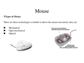
Project Sub-units • This project was divided into three main sub-units: • Device design and fabrication • System integration and driver manipulation • Image acquisition and analysis
Device Circuit Design • Goals of the Clicking Device: • Wireless • Simple Logic • Low Power Consumption • Configurable size • No lag time • Very little noise • Transmission speed that allows rapid double clicking
Design Basics • Two capacitive push buttons send parallel signals that represent the Left and Right mouse clicks • Parallel signals are encoded into a serial signal using an 8 bit shift register. The shift register provides a start and stop code that enclose the LR signals: 010LR010
Design Basics Continued • Shift Register outputs serial signal to a Transmitter which then wireless sends the signal to a Receiver on a different board. • Receiver takes the signal and sends it to a Max232 which converts the voltages into values the serial port will recognize and transfers them via DB9 and RS232 cable to the com port.
555 Timer • Shift register needed a clock frequency that would be recognized by comport and be fast enough to allow a rapid double click. • We chose 2400 bits per second (Hz) • LM 555 Timer allowed us to generate a clock very near this frequency
555 Timer continued Using two resisters of value 1600 Ohms and 2000 Ohms and two capacitors of value .1uF and .01uF, we generated a clock signal of 2576 Hz with a duty cycle 64.3%
Design issues and solutions • After the basic design was completed, there were some problematic issues that needed fixing: • Too much noise • Power source regulation • Square wave generation
Printed Circuit Boards • Once final boards were built and successfully tested, we designed PCBs • Helped with size configuration • Provided more suitable casing options
PCB issues • The PCBs for the clicker and the receiver were never successfully tested • 555 timer • Max232 • Hardwiring • Floating voltages
Testing and Plots • Capacitive button:
Testing and Plots continued • Transmitter to Receiver 2400 Hz:
Testing and Plots continued • Transmitter to DB9 input at 2400 Hz and 20 feet:
Future Improvements • Drag and Drop feature • Miniaturization • USB implementation
System Integration • Serial data read into COM port and analyzed • Relative location of laser pointer acquired from image processing • Integration of these two factors followed by mouse driver manipulation
Serial Port Test HowTo • Hardware: Serial loop back • Software: Reads in data from the serial port and interprets data as Left or Right click
Serial port loopback • Serial port pin diagram
Behind the GUI • Serial Port Settings • Baud Rate: 2400 • Data Bits: 7 • Stop Bit: 1 • Parity Bit: none
SerialPort Class in .Net Framework • Close: Closes the port connection and sets the IsOpen property to false • Open: Opens a new serial port connection • ReadExisting: Reads all immediately available bytes, based on the encoding, in both the stream and the input buffer of the SerialPort object. • Write: Writes data to the serial port output buffer
Process for reading COM port • Open COM port • On data received, read in data from COM port buffer • Interpret data • Close COM port
Reading from Image Processor • clickLocation = detector.point;
Mouse control HowTo • Use import method SendInput of the user32.dll library • DllImport the User32.dll • Remember to add the library using System.Runtime.InteropServices;
Process for Mouse Control • Set Text Left / Right • Set the cursor to memorized location • Set up the INPUT structure • Fill it for mouse down and send the input • Fill it for mouse up and send the input
Image Processing • Logitech QuickCam Fusion • Microsoft DirectShow • 320x240 BitMap • ~8-10 fps • Applied a red filter to camera lens
Image Processing • Every 5 pixels of BitMap is checked • Finds brightest spot in picture
Calibration • Software automatically determines the user’s screen resolution • Define four corners using laser pointer and buttons on GUI • Use corners to determine upper lower, left, and right bounds • Calculate XFactor and YFactor • Convert BitMap location to screen (x, y)
Calibration • XFactor and YFactor ~ 3.5 – 4.5 • Therefore approximately every 20 pixels on the screen is clickable • point = new Point(ScreenX, ScreenY)