Download
1 / 30
300 likes | 448 Views
Putting Formal Description of Software Architecture in Practice: Good News, Bad News. Paola Inverardi. UNIVERSITA’ DEGLI STUDI DELL’AQUILA Area Informatica, Facolta’ di SSMMNN. Brief history of our work in SA. Formal description of SA via CHAM Behavioral Analysis of the SA

E N D
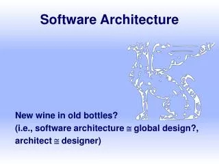
Putting Formal Description of Software Architecture in Practice: Good News, Bad News. Paola Inverardi UNIVERSITA’ DEGLI STUDI DELL’AQUILA Area Informatica, Facolta’ di SSMMNN
Brief history of our work in SA • Formal description of SA via CHAM • Behavioral Analysis of the SA • algebraic analysis and finite state modeling • validation and quantitative analysis based on FSTM
Our experience • Modelling SA for three telecommunication companies • UML as ADL • Poor dynamics descriptions
DYNAMICS • A model of all possible system behaviours • state diagrams for “manageable” processes • implicit parallel notation for composite processes-. P1||P2||…||Pn • No explicit representation due to state explosion • Sequence diagrams/MSCs
ADM ADM ADM ADM ADM ADM ADM ADM ADM ITALIAN TELECOM NETWORK ARCHITECTURE WDM WL WL STM-16 Ring STM-16 Ring ADM ADM ADM ADM ADM ADM ADM ADM ADM National level ADM ADM STM-4/16 STM-4/16 SXA SXA SXC 4/1 SXA ADM ADM STM-1/4 ADM STM-4/16 Regional level ADM ADM STM-1/4 ADM ADM ADM ADM ADM STM-1/4 ADM ADM ADM ADM City level ADM
GOALS • Study of the SXA Cross Connettor. • Development of a SA description (formal / semi-formal) to allow quantitative analysis • Try different description techniques. (UML, ADL, Process Algebras) • The identification and structuring of the information necessary to produce a performance model. • Reverse Engineering. Process
SXA SYSTEM – SOFTWARE CONFIGURATION TLECOMM. PROVIDER OSI STACK COMMAND HANDLER DATABASE MANAGER LOCAL TERMINAL SYSTEM FUNCTION Database MIB XCONN
SXA SYSTEM – HARDWARE CONFIGURATION ET-MUX T-MUX T-MUX ES-CORE working ES-CORE protection ET-MUX T-MUX T-MUX C-CORE Rack IO Rack CENTRAl Rack IO Rack IO
SOFTWARE LAYERS External Interfaces CM DN DR EPS FM LPS TIM TM PM XCONN Global Functions Shelf Functions Periferal Functions Unit Handler System Base Hardware unit
HARDWARE LAYERS ES-CORE Protection C-CORE GLOBAL ES-CORE Working . Timing MSCU MSCU SHELF 8 ETMSU PSCU LAN HUB PERIFERAL C-LAN 2 TSU PSCU 2 TSU PSCU 2 TSU PSCU TDU DPS TDU DPS Phisical ports ASU Phisical ports ASU Phisical ports ASU TDU T-MUX # 1 ET-MUX # 1 T-MUX16 # 1 T-MUX # n < 30 ET-MUX # n < 16 T-MUX16 # n < 8
XCONN LAYERS GXC Global Shelf SSXC CXC TXC BXC STXC SAXC Periferal PTXC PSXC
REVERSE ENGINEERING PROCESS System Domain Study System Function XCONN Domain Study Architectural Description Functional Partition
DOMAIN SYSTEM STUDY Domain System Study Components High-Level Documentation XCONN Domain Study Domain System Study High-Level Sequence Diagrams (UML) Interviews Architectural Description Functional Partition
XCONN DOMAIN STUDY Previous phases Domain System Study Exchanched Messages lists Components detailed description XCONN Domain Study XCONN Domain Study Stereotyped class diagrams (UML) Deployment Diagram (UML) Architectural Description Functional Partition
STEREOTYPED CLASS DIAGRAM (UML) SYSTEM FUNCTION XCONN
ARCHITECTURAL DESCRIPTION Previous activities results System Domain study MSG abstraction Components Detailed Description architectural description XCONN domain study Static description of components with DARWIN SDL Code and Diagrams Architectural description Components Behavioral description by the FSP process algebra Functional partition Feedback on previous activities results
STATIC DESCRIPTION WITH DARWIN Components hierarchy
STATIC DESCRIPTION WITH DARWIN Graphic Description of the SAXC component SAXC cxc[0] cxc[1] bxc[0] bxc[1] txc[1] txc[2] txc[n]
GRAPHIC SDL SDL STATE INPUT MESSAGES OUTPUT MESSAGES
FUNCTIONAL PARTITION System Domain Study Previous activities results XCONN Domain Study Messagge Sequence Chart (MSC) Functional Partition SDL Diagrams and code Architectural Description Activity diagrams (UML) Functional Partition
MESSAGE SEQUENCE CHART (MSC) Components istances automata transition. FSP processes state before performing the action FSP process state after performing the action
Summarizing • Issue of complexity: Have clear in mind what the SA has to be for • Domain specific ADL, complementing standard notations with ad hoc notations, e.g. FSP • Predictive analysis and evaluation of the architectural choices