Download
1 / 108
1.08k likes | 1.09k Views
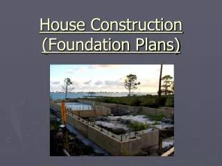
Weekend Cabin Retreat Project Foundations and Foundation Plans. Sacramento City College EDT 300. Objectives. Describe the procedure for staking out a house location. List the major considerations when designing a footing for a residential foundation.

E N D
Weekend Cabin Retreat ProjectFoundations and Foundation Plans Sacramento City College EDT 300 EDT 300 - Foundation Plan Design
Objectives • Describe the procedure for staking out a house location. • List the major considerations when designing a footing for a residential foundation. • Analyze a typical floor plan to determine the appropriate foundation. EDT 300 - Foundation Plan Design
Masonry Foundation EDT 300 - Foundation Plan Design
Wood Foundation EDT 300 - Foundation Plan Design
Staking Out House Location • The plot plan provides the necessary dimensions required for staking out the location of the house on the lot. • Tools for staking out: • Measuring tape • Contractor's level • Transit (if required) EDT 300 - Foundation Plan Design
Staking Out House Location • First Step • locate each corner by laying off the distances indicated on the plot plan. • Drive a stake into the ground at the location of each corner of the foundation to identify its position. EDT 300 - Foundation Plan Design
Staking Out House Location EDT 300 - Foundation Plan Design
Staking Out House Location • Square corners may be laid out using the 9-12-15 unit method. • These proportions define a right triangle and establish a 90 angle corner. EDT 300 - Foundation Plan Design
Staking Out House Location EDT 300 - Foundation Plan Design
Staking Out House Location • Batter boards are used to retain the location of the foundation during excavation and construction. • Are constructed of 2 x 4 stakes driven into the ground about 4 feet outside the footing line. • A 1 x 6 board is nailed horizontally to the stakes so all are level and in the same horizontal plane. (They will have the same elevation.) EDT 300 - Foundation Plan Design
Staking Out House Location EDT 300 - Foundation Plan Design
Staking Out House Location • A strong cord is stretched across the boards at opposite ends of the building and located directly above the corner stakes. • A plumb bob is used for accurate placement of each stake. • This is done for each side of the building. • A saw kerf (cut) is usually made at the exact point on the horizontal batter board where the string is located. • This prevents movement of the string along the board. EDT 300 - Foundation Plan Design
Staking Out House Location • After cuts are made in all eight batter boards, the outlines of the house will be located. • A control point is needed to determine the depth of excavation and foundation wall height. • The corner with the highest elevation is usually selected for this purpose. • The finished floor should be at least 8 inches above the grade. EDT 300 - Foundation Plan Design
Excavation • In excavating for footings and foundation walls, the top soil is usually removed using a bulldozer or tractor with a blade. • This soil is saved for final grading. • A trencher or backhoe may be used to excavate for foundations when either slab construction or a crawl space is planned. EDT 300 - Foundation Plan Design
Excavation • In excavating for a basement, a backhoe used. • Selection of excavating equipment is determined by the size of the excavation and type of soil. • Excavation for footings should extend down to a minimum of 6 in. into undisturbed earth. EDT 300 - Foundation Plan Design
Excavation • It must also be at least 6 in. below the average maximum frost penetration depth. • Local codes usually specify the minimum footing depth for a given area. EDT 300 - Foundation Plan Design
Excavation EDT 300 - Foundation Plan Design
Excavation • No backfilling should be permitted under the proposed footings, because uneven settling of the house may occur. • Footings on rock. About 6 in. of the rock should be removed under the proposed footing and replaced with compacted sand to equalize settling. EDT 300 - Foundation Plan Design
Excavation • Sites which have recently been filled and regraded: the footings should extend down to the original undisturbed earth. • Unless soil tests prove that the earth is sufficiently compacted to properly support the structure. EDT 300 - Foundation Plan Design
Excavation • Excavation must be large enough to allow space to work when constructing the foundation wall and laying drain tile. • The steepness of the back slope will depend on the type of soil encountered. • Sandy soil is likely to cave-in and,requires a gentle back slope. • Clay may be nearly vertical. EDT 300 - Foundation Plan Design
Footing Shapes • Footings increase the supporting capacity of the foundation wall by spreading the load over a larger area. EDT 300 - Foundation Plan Design
Footing Shapes • If a foundation was built on rock, a footing would not be necessary. • Most houses are not built on such solid material and therefore need footings to support the heavy loads. • The size and type of footing should be • suitable for the weight of the building and • soil bearing capacity. EDT 300 - Foundation Plan Design
Footing Shapes • Footings for most residential structures are made of poured concrete. • The size of footing required is commonly determined by using the foundation wall thickness as a basis for its proportions. EDT 300 - Foundation Plan Design
Footing Shapes EDT 300 - Foundation Plan Design
Footing Shapes • This size footing is designed for most normal soil conditions ranging from sand to clay. EDT 300 - Foundation Plan Design
Footing Shapes • Foundation walls should be centered along the footing. • The footing will project beyond each side of the foundation wall a distance equal to one-half the thickness of the foundation wall. • If the soil load bearing capacity is very poor, the size of footings should be increased and reinforced with steel. EDT 300 - Foundation Plan Design
Footing Shapes • The footings must be large enough to minimize the effects of: • settlement of the structure. • unequal compressibility of the soil. • to reduce cracking. • The weight of most homes is greater on two of the four walls which causes unequal loading. EDT 300 - Foundation Plan Design
Footing Shapes EDT 300 - Foundation Plan Design
Foundation Walls • Foundation walls extend from the first floor to the footing. • A foundation wall may also be a basement wall. EDT 300 - Foundation Plan Design
Foundation Walls • Materials used to build foundation walls include • cast (poured) concrete • concrete block • pressure-treated wood • stone or brick in rare instances EDT 300 - Foundation Plan Design
Foundation Walls • Cast concrete and concrete block are widely used in residential structures. • Pressure-treated wood foundations are gaining acceptance for residential structures. • Brick is much more expensive than cast concrete, block, or wood, and is seldom used. • Stone was once used extensively, but is no longer of significance as a foundation material. EDT 300 - Foundation Plan Design
Footing Materials EDT 300 - Foundation Plan Design
Footing Materials EDT 300 - Foundation Plan Design
Footing Materials EDT 300 - Foundation Plan Design
Foundation Walls • Foundation walls are of four basic types: • T-foundation • slab foundation • pier or post foundation • permanent wood foundation EDT 300 - Foundation Plan Design
Foundation Types EDT 300 - Foundation Plan Design
Foundation Types EDT 300 - Foundation Plan Design
Foundation Walls • The type chosen for a particular situation will depend upon • the weight to be supported • load bearing capacity of the soil • location of the foundation in the building • climate • local codes • preferred building practice. • All should be considered when designing a foundation. EDT 300 - Foundation Plan Design
T-Foundations • Most common foundation type • Looks like an inverted T. • The foundation and footing are usually two separate parts but may be cast as a single unit. EDT 300 - Foundation Plan Design
T-Foundations • Concrete for footings of a T-foundation is usually placed in forms made from construction lumber. • The form boards are nailed to stakes once they are level. • Stakes prevent movement while the concrete is being cast. EDT 300 - Foundation Plan Design
T-Foundations EDT 300 - Foundation Plan Design
Slab Foundations • A slab foundation is an extension of a slab floor. • It is placed at the same time the floor is cast and is not a separate unit. • It is sometimes called a thickened edge slab. EDT 300 - Foundation Plan Design
Slab Foundations • The foundation wall should extend down below the frost line, as in the case of the T-foundation. • Use of steel reinforcing bars or mesh is recommended for the slab foundation to prevent cracking due to settling. EDT 300 - Foundation Plan Design
Slab Foundations • Some of the primary advantages of the slab foundation • requires less time, expense, and labor to construct. • no separate footing is required, excavation is not as extensive as for the T-foundation. • Less time is required since the entire foundation and floor is placed in one operation. EDT 300 - Foundation Plan Design
Pier and Post Foundations • Many situations in residential construction lend themselves to the use of piers, columns and posts. • Cheaper and just as satisfactory to use piers rather than the T-foundation under parts of the building. • Example: a crawl space is planned and the distance is too great for a single span, the pier foundation is a logical choice, EDT 300 - Foundation Plan Design
Pier and Post Foundations • Another common application: a basement or garage where the distance is too great to span with floor joists. • Lally columns are used to support a beam that in turn supports the joist., rather than construct a bearing wall partition. EDT 300 - Foundation Plan Design
Pier and Post Foundations • Basic difference between a pier and column is the length. • Piers are usually much shorter and ordinarily located under the house. EDT 300 - Foundation Plan Design
Pier and Post Foundations EDT 300 - Foundation Plan Design