Download
1 / 13
140 likes | 679 Views
Lecture #18 EGR 270 – Fundamentals of Computer Engineering. Reading Assignment: Chapter 7 in Logic and Computer Design Fundamentals, 4 th Edition by Mano . Chapter 7 – Counters and Registers

E N D
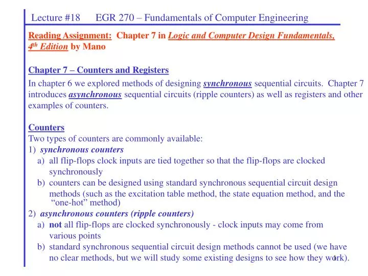
Lecture #18 EGR 270 – Fundamentals of Computer Engineering Reading Assignment: Chapter 7 in Logic and Computer Design Fundamentals, 4th Edition by Mano • Chapter 7 – Counters and Registers • In chapter 6 we explored methods of designing synchronous sequential circuits. Chapter 7 introduces asynchronous sequential circuits (ripple counters) as well as registers and other examples of counters. • Counters • Two types of counters are commonly available: • 1) synchronous counters • a) all flip-flops clock inputs are tied together so that the flip-flops are clocked • synchronously • b) counters can be designed using standard synchronous sequential circuit design • methods (such as the excitation table method, the state equation method, and the “one-hot” method) • 2) asynchronous counters (ripple counters) • a) not all flip-flops are clocked synchronously - clock inputs may come from • various points • b) standard synchronous sequential circuit design methods cannot be used (we have • no clear methods, but we will study some existing designs to see how they work).
Q1 (LSB) Q2 Q3 (MSB) 1 J1 Q1 1 J2 Q2 1 J3 Q3 Clock 1 K1 Q1 1 K2 Q2 1 K3 Q3 Clock Q1 Q2 Q3 Count 0 Lecture #18 EGR 270 – Fundamentals of Computer Engineering Ripple Counters Example 1: Draw a timing diagram for the 4-bit ripple counter shown below in order to determine its counting sequence. Discuss why this is a ripple counter and not a synchronous counter. Begin with count 0.
Q1 (LSB) Q2 Q3 (MSB) 1 J1 Q1 1 J2 Q2 1 J3 Q3 Clock 1 K1 Q1 1 K2 Q2 1 K3 Q3 Clock Q1 Q2 Q3 Count 0 Lecture #18 EGR 270 – Fundamentals of Computer Engineering Ripple Counters Example 2: Repeat Example 1 using positive-edge triggered flip-flops.
Q1 (LSB) Q2 Q3 (MSB) 1 J1 Q1 1 J2 Q2 1 J3 Q3 Clock 1 K1 Q1 1 K2 Q2 1 K3 Q3 Clock Q1 Q2 Q3 Count 0 Lecture #18 EGR 270 – Fundamentals of Computer Engineering Ripple Counters Example 3: Repeat Example 1 clock flip-flopN with Q’N-1 for N > 1.
Q1 (LSB) Q2 Q3 (MSB) 1 J1 Q1 1 J2 Q2 1 J3 Q3 Clock 1 K1 Q1 1 K2 Q2 1 K3 Q3 Clock Q1 Q2 Q3 Count 0 Lecture #18 EGR 270 – Fundamentals of Computer Engineering Ripple Counters Example 4: Repeat Example 3 with positive-edge triggered flip-flops.
Lecture #18 EGR 270 – Fundamentals of Computer Engineering Summary Notes: 1) The type of triggering is often irrelevant with synchronous counters. All of our examples in Chapter 6 (and in lab) could have been built with any type of triggering. 2) The type of triggering used in ripple counters is important and may affect circuit operation. 3) All flip-flops are clocked by the same source (i.e., synchronously) in synchronous circuits. 4) All flip-flops are not clock by the same source in asynchronous (ripple) counters. The choice of the clocking signal for each flip-flop is critical.
Q1 (LSB) Q2 Q3 (MSB) 1 J1 Q1 1 J2 Q2 1 J3 Q3 Clock 1 K1 Q1 1 K2 Q2 1 K3 Q3 Clock Q1 Q2 Q3 Count 0 Lecture #18 EGR 270 – Fundamentals of Computer Engineering Propagation Delay in Ripple Counters - Propagation delay can be a problem in ripple counters at high frequency as the clock signals “ripple” though the circuit. Example 5: Repeat example 1 using an input 10 MHz clock and a propagation delay of 20 ns. PSPICE Example: 3-Bit Ripple Counter (see Bb our course website)
Lecture #18 EGR 270 – Fundamentals of Computer Engineering • Commercially-available Counters • Both synchronous and asynchronous (ripple) counters are available commercially. • 7490 Decade Counter – synchronous counter or ripple counter? • 74190 Up/Down Decade Counter - synchronous counter or ripple counter?
Q1 (LSB) Q2 Q4 Q8 (MSB) 1 J1 Q1 J2 Q2 1 J4 Q4 J8 Q8 Clock 1 K1 Q1 1 K2 Q2 1 K4 Q4 1 K8 Q8 Clock J2 K2 J8 K8 C Q1 Q2 Q3 Q4 Count 0 Lecture #18 EGR 270 – Fundamentals of Computer Engineering Example 6: Use a timing diagram to determine the counting sequence for the ripple counter below. Begin with count 0.
Lecture #18 EGR 270 – Fundamentals of Computer Engineering • Synchronous Counters • Synchronous counters have all flip-flop clock inputs tied together and clocked simultaneously. • Synchronous counter may be designed by: • The excitation table method (covered earlier) • The state equation method (covered earlier) • The “one-hot” method (covered earlier) • By inspection (for relatively simple counters) – covered below • Synchronous Counter Design by Inspection • This method is sometimes useful for simple counter designs. • This method may not yield the simplest solution, but it is typically easy to perform. • Based on the use of T flip-flops (or JK flip-flops in the toggle mode). Determine when each flip-flop must toggle by observing the bit changes in the counting sequence.
Lecture #18 EGR 270 – Fundamentals of Computer Engineering Example: Design a 4-bit synchronous counter using the inspection method and JK flip-flops.
Lecture #18 EGR 270 – Fundamentals of Computer Engineering • N-bit synchronous counter • Show how an n-bit counter can be implemented using N flip-flops and (N-2) two-input AND gates • Discuss the delay problems • Show how the delay can be improved by using ANDs with increasing numbers of inputs
Lecture #18 EGR 270 – Fundamentals of Computer Engineering Example: Design a 4-bit synchronous up/down counter using the inspection method and JK flip-flops. Discuss the amount of work involved in a similar design using the excitation table method.


![DIGITAL DESIGN 3rd edition by MORRIS MANO Chapter 4 Combinational Logic Solutions to the Questions [1-35] DUYGU SA](https://cdn4.slideserve.com/966757/slide1-dt.jpg)