Download
1 / 39
410 likes | 617 Views
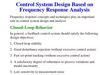
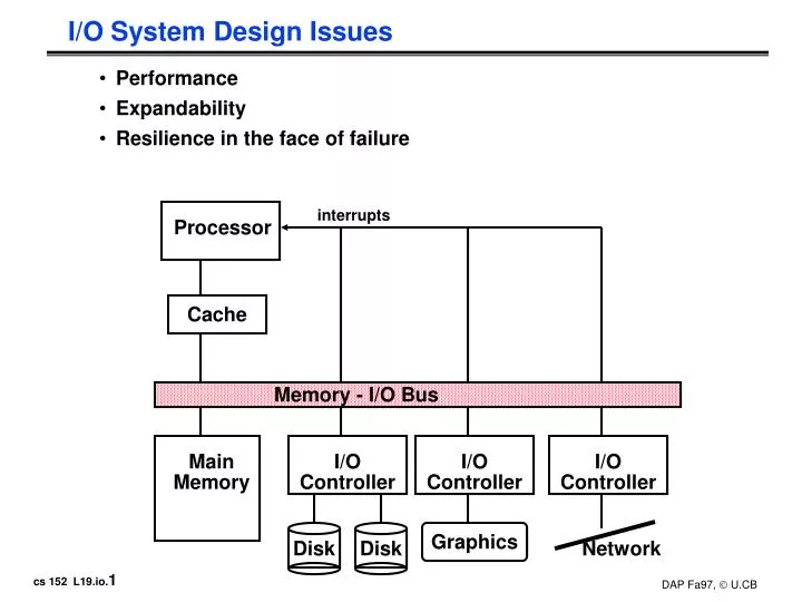
interrupts. Processor. Cache. Memory - I/O Bus. Main Memory. I/O Controller. I/O Controller. I/O Controller. Graphics. Disk. Disk. Network. I/O System Design Issues. Performance Expandability Resilience in the face of failure. I/O Device Examples.

E N D
interrupts Processor Cache Memory - I/O Bus Main Memory I/O Controller I/O Controller I/O Controller Graphics Disk Disk Network I/O System Design Issues • Performance • Expandability • Resilience in the face of failure
I/O Device Examples Device Behavior Partner Data Rate (KB/sec) Keyboard Input Human 0.01 Mouse Input Human 0.02 Line Printer Output Human 1.00 Floppy disk Storage Machine 50.00 Laser Printer Output Human 100.00 Optical Disk Storage Machine 500.00 Magnetic Disk Storage Machine 5,000.00 Network-LAN Input or Output Machine 20 – 1,000.00 Graphics Display Output Human 30,000.00
I/O System Performance • I/O System performance depends on many aspects of the system (“limited by weakest link in the chain”): • The CPU • The memory system: • Internal and external caches • Main Memory • The underlying interconnection (buses) • The I/O controller • The I/O device • The speed of the I/O software (Operating System) • The efficiency of the software’s use of the I/O devices • Two common performance metrics: • Throughput: I/O bandwidth • Response time: Latency
Simple Producer-Server Model • Throughput: • The number of tasks completed by the server in unit time • In order to get the highest possible throughput: • The server should never be idle • The queue should never be empty • Response time: • Begins when a task is placed in the queue • Ends when it is completed by the server • In order to minimize the response time: • The queue should be empty • The server will be idle Producer Queue Server Done
Throughput versus Respond Time Response Time (ms) 300 200 100 20% 40% 60% 80% 100% Percentage of maximum throughput
Throughput Enhancement • In general throughput can be improved by: • Throwing more hardware at the problem • reduces load-related latency • Response time is much harder to reduce: • Ultimately it is limited by the speed of light (but we’re far from it) Server Queue Producer Queue Server Done
Anatomy of an I/O Interface & Output Device Address Lines BUS Data Lines Control Lines I/O Interface Card Also Often Integrated on Motherboard Address Decoder Control Circuits Data Register Status Register I/O Port (e.g RS232) I/O Device
Giving Commands to I/O Devices • Two methods are used to address the device: • Special I/O instructions (e.g. Intel Pentium) • Memory-mapped I/O (virtually everyone else) • Special I/O instructions specify: • Both the device number and the command word • Device number: the processor communicates this via aset of wires normally included as part of the I/O bus • Command word: this is usually send on the bus’s data lines • Often I/O instructions not used in favor of memory mapped I/O • Memory-mapped I/O: • Portions of the address space are assigned to I/O device • Read and writes to those addresses are interpretedas commands to the I/O devices • User programs are prevented from issuing I/O operations directly: • The I/O address space is protected by the address translation
I/O Device Notifying the Processor • The Processor needs to know when: • The I/O device has completed an operation • The I/O operation has encountered an error • This can be accomplished in two different ways: • Polling: • The I/O device put information in a status register • The Processor periodically check the status register • I/O Interrupt: • Whenever an I/O device needs attention from the processor,it interrupts the processor from what it is currently doing.
CPU Memory IOC device Polling: Programmed I/O • Advantage: • Simple: the processor is totally in control and does all the work • Disadvantage: • Polling overhead can consume a lot of CPU time Is the data ready? busy wait loop not an efficient way to use the CPU unless the device is very fast! no yes read data but checks for I/O completion can be dispersed among computation intensive code store data no done? yes
CPU Memory IOC device Interrupt Driven Data Transfer add sub and or nop • Advantage: • User program progress is only halted during actual transfer • Disadvantage, special hardware is needed to: • Cause an interrupt (I/O device) • Detect an interrupt (processor) • Save the proper states to resume after the interrupt (processor) user program (1) I/O interrupt (2) save PC (3) interrupt service addr read store ... rti interrupt service routine : (4) memory
I/O Interrupt • An I/O interrupt is just like the exceptions except: • An I/O interrupt is asynchronous • Further information needs to be conveyed • An I/O interrupt is asynchronous with respect to instruction execution: • I/O interrupt is not associated with any instruction • I/O interrupt does not prevent any instruction from completion • You can pick your own convenient point to take an interrupt • I/O interrupt is more complicated than exception: • Needs to convey the identity of the device generating the interrupt • Interrupt requests can have different urgencies: • Interrupt request needs to be prioritized
SPIM I/O Processor Architecture (1) Coprocessor C0 Holds three registers READ APPENDIX A OF PATTERSON AND HENNESSY!
SPIM I/O Processor Architecture (2) Transmitter Receiver
SPIM I/O Devices (3) Input Keyboard Display Console
Delegating I/O Responsibility from the CPU: DMA • Direct Memory Access (DMA): • External to the CPU • Act as a maser on the bus • Transfer blocks of data to or from memory without CPU intervention CPU sends a starting address, direction, and length count to DMAC. Then issues "start". CPU Memory DMAC IOC device DMAC provides handshake signals for Peripheral Controller, and Memory Addresses and handshake signals for Memory.
Delegating I/O Responsibility from the CPU: IOP D1 IOP CPU D2 main memory bus Mem . . . Dn I/O bus target device where cmnds are OP Device Address CPU IOP (1) Issues instruction to IOP (4) IOP interrupts CPU when done IOP looks in memory for commands (2) OP Addr Cnt Other (3) memory what to do special requests Device to/from memory transfers are controlled by the IOP directly. IOP steals memory cycles. where to put data how much
OS Scheduler Maintaining the Processor Busy While I/O Finishes Key Idea: Run multiple programs (processes) simultaneously OS Job: Keep processor busy (aka LOADed) doing USEFUL work Process Requests I/O Processes Awaiting I/O Interrupt Handler Ready Queue Often Prioritized
Responsibilities of the Operating System • The operating system acts as the interface between: • The I/O hardware and the program that requests I/O • Three characteristics of the I/O systems: • The I/O system is shared by multiple program using the processor • I/O systems often use interrupts (external generated exceptions) to communicate information about I/O operations. • Interrupts must be handled by the OS because they cause a transfer to supervisor mode • The low-level control of an I/O device is complex: • Managing a set of concurrent events • The requirements for correct device control are very detailed
Operating System Requirements • Provide protection to shared I/O resources • Guarantees that a user’s program can only access theportions of an I/O device to which the user has rights • Provides abstraction for accessing devices: • Supply routines that handle low-level device operation • Handles the interrupts generated by I/O devices • Provide equitable access to the shared I/O resources • All user programs must have equal access to the I/O resources • Schedule accesses in order to enhance system throughput
OS and I/O Systems Communication Requirements • The Operating System must be able to prevent: • The user program from communicating with the I/O device directly • If user programs could perform I/O directly: • Protection to the shared I/O resources could not be provided • Three types of communication are required: • The OS must be able to give commands to the I/O devices • The I/O device must be able to notify the OS when the I/O device has completed an operation or has encountered an error • Data must be transferred between memory and an I/O device
Multimedia Bandwidth Requirements • High Quality Video • Digital Data = (30 frames / second) (640 x 480 pels) (24-bit color / pel) = 221 Mbps (75 MB/s) • Reduced Quality Video • Digital Data = (15 frames / second) (320 x 240 pels) (16-bit color / pel) = 18 Mbps (2.2 MB/s) • High Quality Audio • Digital Data = (44,100 audio samples / sec) (16-bit audio samples) • (2 audio channels for stereo) = 1.4 Mbps • Reduced Quality Audio • Digital Data = (11,050 audio samples / sec) (8-bit audio samples) (1 audio channel for monaural) = 0.1 Mbps • compression changes the whole story!
Multimedia and Latency • How sensitive is your eye / ear to variations in audio / video rate? • How can you ensure constant rate of delivery? • Jitter (latency) bounds vs constant bit rate transfer • Synchronizing audio and video streams • you can tolerate 15-20 ms early to 30-40 ms late
Summary: • I/O performance is limited by weakest link in chain between OS and device • Disk I/O Benchmarks: I/O rate vs. Data rate vs. latency • Three Components of Disk Access Time: • Seek Time: advertised to be 8 to 12 ms. May be lower in real life. • Rotational Latency: 4.1 ms at 7200 RPM and 8.3 ms at 3600 RPM • Transfer Time: 2 to 12 MB per second • I/O device notifying the operating system: • Polling: it can waste a lot of processor time • I/O interrupt: similar to exception except it is asynchronous • Delegating I/O responsibility from the CPU: DMA, or even IOP • wide range of devices • multimedia and high speed networking poise important challenges
Magnetic Disk • Purpose: • Long term, nonvolatile storage • Large, inexpensive, and slow • Lowest level in the memory hierarchy • Two major types: • Floppy disk • Hard disk • Both types of disks: • Rely on a rotating platter coated with a magnetic surface • Use a moveable read/write head to access the disk • Advantages of hard disks over floppy disks: • Platters are more rigid ( metal or glass) so they can be larger • Higher density because it can be controlled more precisely • Higher data rate because it spins faster • Can incorporate more than one platter Registers Cache Memory Disk
Organization of a Hard Magnetic Disk • Typical numbers (depending on the disk size): • 500 to 2,000 tracks per surface • 32 to 128 sectors per track • A sector is the smallest unit that can be read or written • Traditionally all tracks have the same number of sectors: • Constant bit density: record more sectors on the outer tracks • Recently relaxed: constant bit size, speed varies with track location Platters Track Sector
Magnetic Disk Characteristic Track • Cylinder: all the tacks under the head at a given point on all surface • Read/write data is a three-stage process: • Seek time: position the arm over the proper track • Rotational latency: wait for the desired sectorto rotate under the read/write head • Transfer time: transfer a block of bits (sector)under the read-write head • Average seek time as reported by the industry: • Typically in the range of 8 ms to 12 ms • (Sum of the time for all possible seek) / (total # of possible seeks) • Due to locality of disk reference, actual average seek time may: • Only be 25% to 33% of the advertised number Sector Cylinder Platter Head
Typical Numbers of a Magnetic Disk Track Sector • Rotational Latency: • Most disks rotate at 3,600 to 7200 RPM • Approximately 16 ms to 8 ms per revolution, respectively • An average latency to the desiredinformation is halfway around the disk: 8 ms at 3600 RPM, 4 ms at 7200 RPM • Transfer Time is a function of : • Transfer size (usually a sector): 1 KB / sector • Rotation speed: 3600 RPM to 7200 RPM • Recording density: bits per inch on a track • Diameter typical diameter ranges from 2.5 to 5.25 in • Typical values: 2 to 12 MB per second Cylinder Platter Head
I/O Benchmarks for Magnetic Disks • Supercomputer application: • Large-scale scientific problems => large files • One large read and many small writes to snapshot computation • Data Rate: MB/second between memory and disk • Transaction processing: • Examples: Airline reservations systems and bank ATMs • Small changes to large shared software • I/O Rate: No. disk accesses / second given upper limit for latency • File system: • Measurements of UNIX file systems in an engineering environment: • 80% of accesses are to files less than 10 KB • 90% of all file accesses are to data with sequential addresses on the disk • 67% of the accesses are reads, 27% writes, 6% read-write • I/O Rate & Latency: No. disk accesses /second and response time
Disk I/O Performance Request Rate • Disk Access Time = Seek time + Rotational Latency + Transfer time + Controller Time + Queueing Delay • Estimating Queue Length: • Utilization = U = Request Rate / Service Rate • Mean Queue Length = U / (1 - U) • As Request Rate -> Service Rate • Mean Queue Length -> Infinity Service Rate l m Disk Controller Disk Queue Processor Disk Controller Disk Queue
Example • 512 byte sector, rotate at 5400 RPM, advertised seeks is 12 ms, transfer rate is 4 BM/sec, controller overhead is 1 ms, queue idle so no service time • Disk Access Time = Seek time + Rotational Latency + Transfer time + Controller Time + Queueing Delay • Disk Access Time = 12 ms + 0.5 / 5400 RPM + 0.5 KB / 4 MB/s + 1 ms + 0 • Disk Access Time = 12 ms + 0.5 / 90 RPS + 0.125 / 1024 s + 1 ms + 0 • Disk Access Time = 12 ms + 5.5 ms + 0.1 ms + 1 ms + 0 ms • Disk Access Time = 18.6 ms • If real seeks are 1/3 advertised seeks, then its 10.6 ms, with rotation delay at 50% of the time!
Magnetic Disk Examples Characteristics IBM 3090 IBM UltraStar Integral 1820 Disk diameter (inches) 10.88 3.50 1.80 Formatted data capacity (MB) 22,700 4,300 21 MTTF (hours) 50,000 1,000,000 100,000 Number of arms/box 12 1 1 Rotation speed (RPM) 3,600 7,200 3,800 Transfer rate (MB/sec) 4.2 9-12 1.9 Power/box (watts) 2,900 13 2 MB/watt 8 102 10.5 Volume (cubic feet) 97 0.13 0.02 MB/cubic feet 234 33000 1050
Reliability and Availability • Two terms that are often confused: • Reliability: Is anything broken? • Availability: Is the system still available to the user? • Availability can be improved by adding hardware: • Example: adding ECC on memory • Reliability can only be improved by: • Bettering environmental conditions • Building more reliable components • Building with fewer components • Improve availability may come at the cost of lower reliability
Disk Arrays • A new organization of disk storage: • Arrays of small and inexpensive disks • Increase potential throughput by having many disk drives: • Data is spread over multiple disk • Multiple accesses are made to several disks • Reliability is lower than a single disk: • But availability can be improved by adding redundant disks (RAID):Lost information can be reconstructed from redundant information • MTTR: mean time to repair is in the order of hours • MTTF: mean time to failure of disks is tens of years
Optical Compact Disks • Disadvantage: • It is primarily read-only media • Advantages of Optical Compact Disk: • It is removable • It is inexpensive to manufacture • Have the potential to compete with newtape technologies for archival storage
P1394 High-Speed Serial Bus (firewire) • a digital interface – there is no need to convert digital data into analog and tolerate a loss of data integrity, • physically small - the thin serial cable can replace larger and more expensive interfaces, • easy to use - no need for terminators, device IDs, or elaborate setup, • hot pluggable - users can add or remove 1394 devices with the bus active, • inexpensive - priced for consumer products, • scalable architecture - may mix 100, 200, and 400 Mbps devices on a bus, • flexible topology - support of daisy chaining and branching for true peer-to-peer communication, • fast - even multimedia data can be guaranteed its bandwidth for just-in-time delivery, and • non-proprietary • mixed asynchronous and isochornous traffic
Firewire Operations • Fixed frame is divided into preallocated CBR slots + best effort asycnhronous slot • Each slot has packet containing “ID” command and data • Example: digital video camera can expect to send one 64 byte packet every 125 µs • 80 * 1024 * 64 = 5MB/s Packet Frame = 125 µsecs isochronous channel #1 time slot isochronous channel #1 time slot Time slot available for asynchronous transport Timing indicator