Download
1 / 2
20 likes | 107 Views
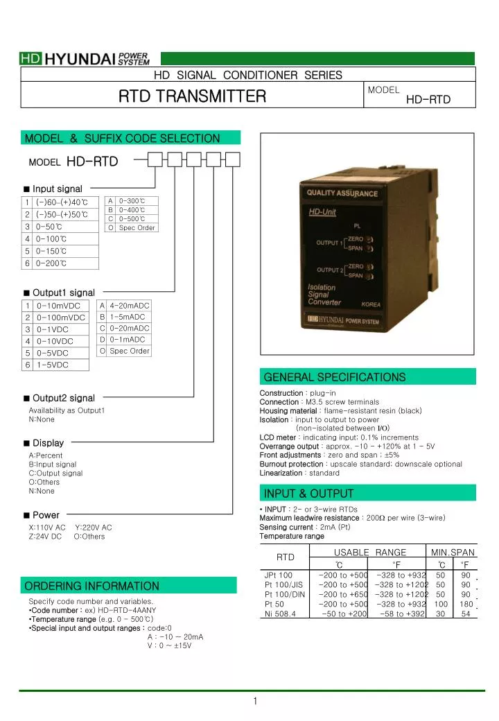
HD SIGNAL CONDITIONER SERIES. RTD TRANSMITTER. MODEL HD-RTD. MODEL & SUFFIX CODE SELECTION. HD-RTD. MODEL. Input signal. Output1 signal. GENERAL SPECIFICATIONS. Construction : plug-in Connection : M3.5 screw terminals Housing material : flame-resistant resin (black)

E N D
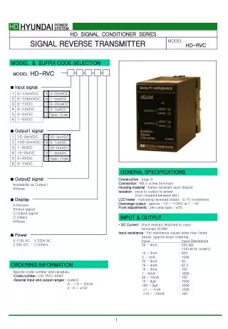
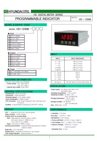
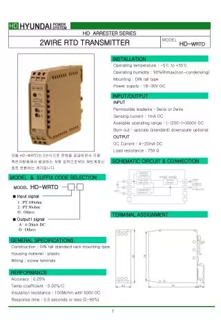
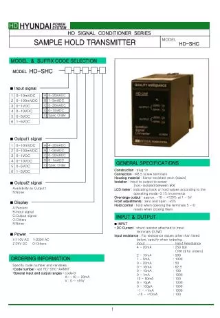
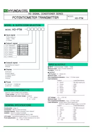
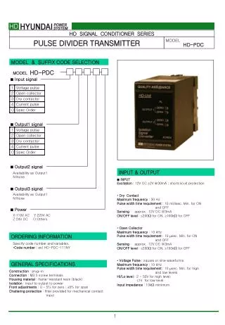
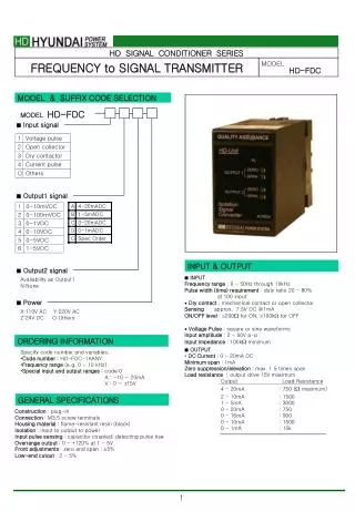
HD SIGNAL CONDITIONER SERIES RTD TRANSMITTER MODEL HD-RTD MODEL & SUFFIX CODE SELECTION HD-RTD MODEL • Input signal • Output1 signal GENERAL SPECIFICATIONS Construction : plug-in Connection : M3.5 screw terminals Housing material : flame-resistant resin (black) Isolation : input to output to power (non-isolated between I/O) LCD meter : indicating input; 0.1% increments Overrange output : approx. -10 - +120% at 1 - 5V Front adjustments : zero and span ; 5% Burnout protection : upscale standard; downscale optional Linearization : standard • Output2 signal Availability as Output1 N:None • Display A:Percent B:Input signal C:Output signal O:Others N:None INPUT & OUTPUT • INPUT : 2- or 3-wire RTDs Maximum leadwire resistance : 200 per wire (3-wire) Sensing current : 2mA (Pt) Temperature range • Power X:110V AC Y:220V AC Z:24V DC O:Others ORDERING INFORMATION Specify code number and variables. • Code number : ex) HD-RTD-4AANY • Temperature range (e.g. 0 - 500℃) • Special input and output ranges : code:0 A : -10 ~ 20mA V : 0 ~ 15V
OUTPUT • DC Current : 0 - 20mA DC Minimum span : 1mA Zero suppression/elevation : max. 1.5 times span Load resistance Output Load Resistance 4 - 20mA : 750 ( maximum) 2 - 10mA : 1500 1 - 5mA : 3000 0 - 20mA : 750 0 - 16mA : 900 0 - 10mA : 1500 0 - 1mA : 15k • DC Voltage : -10 - +12V DC Minimum span : 5mV Zero suppression/elevation : max. 1.5 times span Load resistance : output drive 10mA maximum; 5mA for negative voltage output; at 0.5V Output Load Resistance 0 - 10mV : 10k ( minimum) 0 - 100mV : 100k 0 - 1V : 100 0 - 10V : 1000 0 - 5V : 500 1 - 5V : 500 INSTALLATION Power input AC : rating 10%, 50/60 2 Hz, approx. 2VA DC : rating 10% , or 85 - 150V for 110V rating (ripple 10% p-p max.) approx. 2W (80mA at 24V) Operating temperature : -5 to +60℃ (23 to 140℉) Operating humidity : 30 to 90% RH (non-condensing) Mounting : surface or DIN rail Dimensions : W50 H80 D123 mm See General Spec. Sheet Page B-1. Weight : Terminal assignment : See General Spec. Sheet Page B-1. PERFORMANCEin percentage of span Accuracy : 0.2% Temp. coefficient : 0.015%/℃ (0.008%/℉) Ripple : 0.25% p-p max. (100/120Hz) Response time : 0.4(400ms) seconds (0 - 90%) approx. 25 milliseconds with option Burnout response : 10 seconds Line voltage effect : 0.1% over voltage range Insulation resistance : 100MΩ with 500V DC Dielectric strength : 1500V AC @1 minute (RB : input or output to power to ground) (RBS : input to output to power to ground) Common mode voltage : 30V RMS (CSA) Surge withstand Voltage : 1.2/50sec, 5KV (INPUT to OUTPUT to GROUND) SCHEMATIC CIRCUITRY & CONNECTION DIAGRAM