Download
1 / 27
270 likes | 272 Views
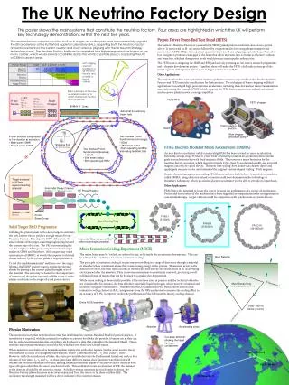
Neutrino Factory, ± Decay Rings. C Johnstone, FNAL, F Meot, CNRS, & G H Rees, RAL. 20 GeV Isosceles Triangle Rings (2). Apex α. Neutrinos. Neutrinos. ± injections. End bend. Collimation, rf and tune change. 50 GeV Isosceles Triangle Rings (2). ξ correction in 5-cell sets.

E N D
Neutrino Factory, ±Decay Rings C Johnstone, FNAL, F Meot, CNRS, & G H Rees, RAL
20 GeV Isosceles Triangle Rings (2) Apex α Neutrinos Neutrinos ± injections End bend Collimation, rf and tune change
50 GeV Isosceles Triangle Rings (2) ξ correction in 5-cell sets 16/11 cell arc, Q=3.2/2.2 Solenoid focusing Production straights may be extended 10 cell arc, Q=2 10 cell arc, Q=2
Triangle Ring Design Changes • Change from equilateral to an isosceles triangle ring. • Design for MW intensities: βγA = 30 (1.5)2 (π mm r) • Use box-car stacking for trains of 80 μ+ & μˉ bunches. • Introduce a beam loss collection system for muons. • Use combined not separated function magnets in arcs. • Use solenoid focusing in the two production straights. • Use bend units at the ends of the production straights. • Use matching section bends to suppress dispersion • (these influence the production straight orientations). • Modify the lattice when upgrading from 20 to 50 GeV. • Change some magnets and re-align ring for 50 GeV.
Decay Ring Triangle Apex Angles Numbers of arc cells determine triangle apex angles. Five cell groups are used for the chromaticity control. Arc cells Apex angles Circ. Prod. st. RF harmonic Efficiency (º) (m) (m) (h) (%) 10+10+10 ~60.0 1573.05 364.0 25 x3 x11 2 x 23.1 10+10+11 ~52.8 1573.05 378.0 25 x3 x11 2 x 24.0 10+10+12 ~45.0 1525.38 388.0 210 2 x 25.4 11+11+15 ~34.5 1525.38 412.2 210 2 x 27.0 10+10+16 ~22.4 1573.05 465.5 25 x3 x11 2 x 29.6 Note: Detectors at 7500 & 3500 km need apex angles of ~ 50°.
Proton and Muon, n =5, 50 Hz Bunch Trains O Proton booster (n=5, h=6)O O O O O Proton driver (n=5, h=36)O O O O Proton bunches at target O O O O T O Pion bunches after target O O O O O Muon, 400 ns bunch trains (n-1)T< 60 μs (liquid target)T T > 60 μs (for solid targets)μˉ 20 GeV μ+ & μˉ accelerator μ+ 20/50 GeV μ+ decay ring 600 600 600 C>1500 m circumference 400 ns bunch trains & > 600(+) ns gaps 20/50 GeV μˉ decay ring 600 600
Ring Harmonic Numbers Rings Beta Circ (m) hRF (MHz) Nb /Ring 50 GeV μ Decay 0.9999977 1573.0691 1056201.250 5x80 20 GeV μ Decay 0.9999861 1573.0509 1056201.250 5x80 8-20 GeV μ± Acc 0.9999861 1135.0991 762 201.250 10x80 3.2-8 GeV μ± Acc 0.9999150 201.250 10x80 1-3.2 GeV μ± Acc 0.9994890 201.250 10x80 3-10 GeV P Driver 0.9963143 801.44744 36 13.079-13.417 5 216 80.500 5 540 201.250 5 0.18-3 GeV Booster 0.9712057 400.72372 6 2.4422-4.3595 5
Box-car Transfer of μ+ & μˉ to Decay Rings The 20 GeV decay rings, 8-20 GeV μ±acc & P driver, of periods Td , Ta , Tp , all have 201.25 MHz as a harmonic. The integers p (= 1,2,3 ,4), n and m are chosen so the proton bunch delaysare a good approximation to: (n ± p/5) Td≈(m ± 1/12) Tp Td , Ta , Tp = 5.2472044, 3.7863345, 2.6832296 μs, (Td /Tp) = 1.9555554 Target m n p(m ± 1/12) (n ± p/5)(Td /Tp)|Difference| Solid 23 12 -1 23 + 0.083333 23.075553 0.007780 Liquid 5 3 -2 5 + 0.083333 5.084444 0.001111 For solid target:(m + 1/12) Tp = n Td -207Tb (RF period Tb ) For liquid target: (m + 1/12) Tp = n Td - 423Tb
N=5, Muon Bunch Pattern in Decay Rings > 100ns intervals . 80 μ+ 127(130) 148(136) solid/liquid 80 μ+ 127(130) 2 of 5 interleaved 80 μˉ bunchtrains of 2nd ring 80 μ+ 80 μ+ 127(!30) 80 μ+ 127(130) 80 full and 127 (or 130) empty RF buckets
Other Triangle Ring Options • A wider range of apex angles may be obtained by adding half cells in one or more of the arcs. 2. Production straights may have different lengths, but ξ gain of longer is < loss in ξ of the latter. 3. For specified detector distances, the smallest apex angle is for a triangle in a vertical plane. 4. Smaller circumference rings may be considered with n reduced from 5 to 4, 3 or 2 bunch trains.
Efficiencies for Smaller Decay Rings Circumference (m) Prod St (m) Efficiency Racetrack 1573.05 2 x 378.0 48.0% 38% 1258.44 2 x 268.0 42.6% 35% 943.83 2 x 156.9 33.2% 30% 629.22 2 x 14.84.7%20% Each reduction in circumference lowers the efficiency and, for the last case, a racetrack is the more efficient. There is concern for the > 400 m depths of triangle and racetrack rings, at the circumference of 1573 m.
Vertical Plane Triangle Ring ν . αθ ν Apex ν sin α = L1 /2Rsin θ = L2 /2R L1, L2 detector distances R the equatorial radius L1 L2 Apex angle (α+ θ) 3500 km 7500 km ~ 52.0° 2500 km 7500 km ~ 47.5°
Site Examples NuFact Detector 1 Detector 2 Apex α Vert. tilt BNL Carlsbad Arlit (7369 km) 48.4° 0.9° (2883 km) RAL Carlsbad Baksan (3375 km) 60.2° 33.9° (7513 km) Cyprus (3251 km) 51.7° 10.7° Crete (2751 km) 48.6° 1.0°
Muon Beam Loss Collection Due to the e±losses after ±decays, the warm bores of S/C arc magnets have to be cooled, & clad with Pb. (The cladding absorbs > 80% of the e± beam power.) Direct ± wall loss also leads to magnet heating, and to minimise this, ± loss collection is proposed, with primary and secondary collimators in 4 FODO cells at the centre of the short straight section of the ring, Primary collimators are set for : βγA = 30 (π mm r). The ring acceptances are: βγA = 30 (1.5)2 (π mm r).
Arc Cell Design CERN 10,10,10 FODO design: Lengths = 9.703, 0.7 m, = π/2, βmax = 16.6 m, Dmax = 1.4 m. New 10,10,16 BFOBDO, FFAG design: Lengths = 7.80, 1.4 m, = 2π/5, βmax = 12.1 m, Dmax = 1.2 m. (space for cryostat ends, valves, correctors, diagnostics, vacuum & cooling)
Production Straight Focusing A figure of merit for lattice focusing is: 1 / (γβmax ) For a thin lens FODO: γβmax = 2/(1 - sin μ/2) > 2 For an OSO lattice of weak solenoids: γβmax ≈ I So, the OSO cell has a 50% lower value for βmax. For 52.8°, use 8, 4.75 m units in 378.0 m straights: At 20 GeV, βmax ≈ 99 m for solenoids with 4.3 T. At 50 GeV, βmax ≈ 163 m for solenoids with 6.4 T.
Neutrino Production Straights 20 GeV 50 GeV Muon norm rms emitt (π mm r) 4.80 4.80 μ to ν divergence angle ratio, R 0.098 0.119 Number of solenoids 8 8 Solenoid fields (T) 4.272 6.369 Length of solenoids (m) 4.75 4.75 Half of inter space (m) 16.8 16.8 β value at beam waist (m) ~94.3 ~160.3 β (max) in solenoid (m) ~99.1 ~163.1
Effect of Production Region End Bends Neutrinos, from ± beyond the bends, miss detectors. Bends introduce dispersion, however, into the lattice. Matching of dispersion to arcs requires further bends, which are different for the 20 and the 50 GeV lattices. Small changes in the arc bend angles are required to preserve the orientation of the 2 production straights. Dispersion in the third straight is also affected and modified matching is needed for the 50 GeV upgrade.
Storage Ring Parameters Efficiencies for 22.4° apex Δ: 2 x 29.6 % Efficiencies for 52.8° apex Δ: 2 x 24.0 % Production straights of above: 465.5, 378.0 m Decay rings’ circumference: 1573.1 m μtoνangle ratio at 20 GeV: 0.098 μtoνangle ratio at 50 GeV: 0.119 Max β in the ring at 20 GeV: 117.0 m Max β in the ring at 50 GeV: 184.0 m Qh andQv values at 20 GeV: 13.367, 13.184 Qh and Qv values at 50 GeV: 13.187, 12.817
First Tracking of 22.4°, 1170.8 m, 20 GeV Ring On-momentum muons: Horizontal εn = 60 (π) mm rad only, Qh = 10.79 -10.80 Vertical εn = 60 (π) mm rad only, Qv = 11.147 - 11.155 Hor. & vert. εn = 30 (π) mm rad, Qh ,Qv= 10.81, 11.166 Effect of the solenoid ( +-+-+-+- ) coupling is small. Off-momentum muons: Δp/p = 0.5%, hor. & vert. εn = 60 (π) mm rad; stable. Δp/p = 1.0%, h. & v. εn = 45 (π) mm rad; just unstable. Qv decreases to 11.0, in agreement with ξv estimates.
Injection of n Trains of 80 ±Bunches Long neutrino production straight section . Solenoid 1 Solenoid 2 Solenoid 3 Injection septum Train of 80, or bunches Fast kicker magnets, K Superconduc-ting solenoids K stored energy/power is large due to the big acceptance & the ~ 600 ns rise & fall times for the 1573.1 m circumference ring, which has n (= 5) injected bunch trains per 50 Hz cycle. Induction kickers may be needed for the upgrade to 50 GeV.
Injection System Parameters Inject at upstream end of long straight nearest surface. k≈√βk (√A + √ε + ts /√βs) / (βk sin Δμ + ½ NL cos Δμ) NL I (number, length, current) = 2 (Bρ) k√(A βv )/ μo NT V (number, rtime, voltage) = 2 (Bρ) k√(A βk ) At 20 GeV, for A, ε = 354.7, 157.7 mm mr, ts = 15 mm, βs≈βk≈βv≈95.0 m, Δμ≈25°, Bρ=67.064 T m, T= 435 ns: Use 8, shorted, 3m, 10 Ω delay line, push pull K with 16, 50 kV PFN; 16, 5 kA pulsers and 16, 10 Ω feeders. NL = 24 m, k = 6.47 mr, I = 5000 A, NT V = 0.16 V s
Longitudinal Motion and RF RF needed to keep 100 ns gaps if n=5, but not if n<5. Injected bunch trains are tilted in longitudinal phase space & rotate in RF cavity & wall impedance fields. Injected bunches are allowed to expand in phase until Δφ = ± π/2 rad, for Δp/p = ± 0.01 Required are 30 MV, 201 MHz containing fields/ ring. The required net RF containing field scales as (Δp/p)2 and the dynamic aperture also improves at lower Δp/p.
RF System for Rings Inductive wall fields are defocusing as γ > γt . Fields become small after the bunches expand. Reactive beam loading comp.; cavities on tune. Loading alters after each injected bunch train. Reflected power dissipated in circulator loads. The peak power for n = 5 is ~ 5.4 MW per ring. So, for 2x1 MW input couplers: 3 cavities/ring.
Design Summary An outline design has been made for 2, isosceles triangle, 20 (potentially 50) GeV, ±storage rings. For a single detector, 2 racetrack rings are preferred. For 2 detectors, 2 vertical triangle rings have higher ξ. C = 1573.1 m, L = 378 m, ξ = 2 x 24.0%, 52.8° apex Δ. C = 1258.4 m, L = 268 m, ξ = 2 x 21.3%, 52.8° apex Δ. The MW rings have large βγA, at 30 (1.5)2 (π mm r). Production straight solenoids give lower beam sizes. μtoνangle ratios are 0.10 & 0.12, at 20 & 50 GeV. F Meot is tracking to find dynamic aperture with errors. Injection difficult for uncooled (45 π mm r) ±beams.