Download
1 / 26
260 likes | 264 Views
R&D for SLHC detectors at PSI and Geneva . CHIPP workshop on the high-energy frontier of particle physics Z ü rich 6. September 2006 R. Horisberger (Paul Scherrer Institut) A. Clark (University of Geneva). Super LHC machine ~ 10x Luminosity.

E N D
R&D for SLHC detectors at PSI and Geneva CHIPP workshop on the high-energy frontier of particle physics Zürich 6. September 2006 R. Horisberger (Paul Scherrer Institut) A. Clark (University of Geneva)
Super LHC machine~ 10x Luminosity • various upgrade phases for LHC machine possible: • phase 0/1 limited hardware upgrade 3 - 5 x 10 34 cm-2 sec-1 • phase 2 major hardware upgrade 10 x 10 34 cm-2 sec-1 • Present CMS/ATLAS tracking systems built for integrated fluence ~ 500 fb-1 • Assume for SHLC operation 2500 fb-1 and L= 5x or 10x 10 34 cm-2 sec-1 • Tracker upgrade stage should be available in 2013/14 • With 4 years of qualification / production 3-4 years of R&D ! Little time! • SLHC challenge: Data rates & Radiation Damage
Expected SLHC Environment ATLAS 230 min.bias collisions in bunch ~10000 particles in || 3.2 mostly low pT tracks Nch(|y|0.5)
ATLAS & CMS had several internal workshops to study and address the new challenge • e.g. • CMS Conclusions • Design & built new ~200 m2Silicon Pixel Tracker for SLHC with: • - Momentum resolution • - Material budget • - Tracking efficiency • equal or better than present tracker under LHC conditions • need L1 trigger from tracking system
CMS Silicon Tracker LHCSLHC Silicon Pixel Detector Occupancy: 10-4 10-3 ~ 1 m2 Data 0-Sup: yes yes Silicon StripDetector Occupancy: 1-4% 10-40% ~ 220 m2 Data 0-Sup: no no Present Silicon Strip Tracker (SST) needs replacement with zero-suppressed Pixel Tracker Pixel / Strixel / Striplets name not clear defined, depends on L/W
CMS Muon Rate at L = 1034 From DAQ TDR Note limited rejection power (slope) without tracker information New CMS Pixel Tracker needs trigger capability !
CMS Detector Replacements SLHC Pixel Tracker Materials Cost for Collaboration (CORE) Across collaboration ~ 900 FTE J. Nash , CMS Electronics Coordinator
SLHC needs consistent professional work on several areas: • Radiation damage on silicon sensors RD50 • low power electronics conception & design CMOS 0.25mm 0.13mm ?? • high bandwidth controls & data readout replace TTC system • 40MHz AOH readout • low cost design / low cost fabrication of pixel modules • low mass power distribution scheme serial powering • rad. hard regulators • low mass cooling • low mass construction less material more alignment • low mass cabling very high bandwidth serial protocols
Power consumption~ material budget • Current consumption: Analog: Strips reduce noise • Pixels speed (timewalk) • Digital: Information processing (data flow) ~ fluence • Reduce power by : - Technology - CMOS 0.25m 0.13m digital: yes • analog: no • - Architecture choice Pixel ROC Power/cm2: ALICE 100% • ATLAS 72% • CMS 31% • - Custom protocols TBM05 ~ 1/6 power of TBM03 • abandon LVDS for 5cm distance custom • protocol LCDS (Low Current Differential Swing)
Potential Common R&D • Power • Target DC-DC conversion • Serial powering also an option • A new control system for the LHC experiements • Replace the TTC system • Some current prototypes “gbt” being developed in MIC • Vital that CMS/ATLAS requirements are well defined as input to this development • Top down, not bottom up system design J. Nash , CMS Electronics Coordinator
R&D II • Optical Links • Radiation of components • Interfaces to control system • IP blocks for 130nm • Build a radiation tolerant library in next generation CMOS technology • Potentially create some useful building blocks for development of next generation ASICs J. Nash , CMS Electronics Coordinator
To do list for Super LHC tracker: • 1) Adapt and modify present pixel detector and its technology for SLHC operation at small radii ( r = 7 – 20cm ) • 2) Develop and design new low cost, pixel technologies for medium ( r = 20 – 50cm ) and large radii ( r = 50 - 120 cm )
PSI / ETHZ / Uni ZH / Uni BS have developed bulk of present pixel detector and has aquired following expertises: • Micro-bump bonding (develop 18m In-bumps) TEM,LMN,LNS • CMOS Read Out Chip design (1989-2006 ~ 55 Chips designed @ PSI) • ROC testing ( ~ 30K ROC tested by ETHZ ) • Silicon sensor design & semiconductor simulation (PSI) • Sensor testbeams at CERN (Univ. ZH, PSI) • LHC rate ROC testbeams (PSI, pE1 beam line) • Pixel module assembly (PSI / ETHZ) • Pixel module qualification (U. Langenegger et al. ETHZ) • Low mass mechanics & Cooling (Univ. ZH) • System Integration & Cabling (PSI) CH Pixel Team is likely to perform task number 1) and be helpful to CMS collaboration for task 2) with selected contributions due to its unique pixel experience. e.g. Pixel ROC evolution to high LHC rates Low cost bump – bonding
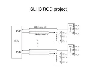
sketch of a double column 7.8mm hit pixel unit cells: 2x80 data double column fast double column OR column drain mechanism 9.8mm double pixels set double column interface Time-stamp buffer Depth: 12 data buffer Depth: 32 32 data buffers marker bits indicate start of new event 12 time stamp buffers CMS Pixel ROC: Column Drain Architecture chip size ! SLHC rate data losses dominated by finitebuffer sizes !
Measurement in X-ray box • Very high photon fluence up to 300MHz/cm2 • Single chip sensor • No TBM • -> short readout times, readout losses negligible (see later) • Simulation agrees very well with measurement LHC (1034cm-2s-1): 11cm 7cm 4cm
Contributions to data loss • Entirely dominated by timestamp buffer overflows • In experiment also data buffer overflow (higher pixel multiplicity) • Steep rise of inefficiency due to buffer limitations LHC (1034cm-2s-1): 11cm 7cm 4cm
Doubling the buffer size mounting screw whole 0.4mm new ROC size Doubling the buffer size in current 0.25mm ROC results in an increase of the periphery of 800mm just possible No R&D needed. Design ready in 1 month
Future TBM Read Out Scheme Present TBM Read Out Scheme Evolutionary upgrade of CMS pixel modules • CMS pixel modules need to be replaced. ( r=4cm every 2 years @ 1034) • LHC SLHC has probably no sharp step in luminosity • Can improve rate capability of present pixel modules by: • - increase buffer size in ROC periphery (factor 2 in 0.25mm CMOS ) • - extra data buffer in redesigned TBM with parallel ROC read out scheme • Replaced modules would be fully compatible with present system. • allows operation of present pixel system at L ~ 3x10 34 cm-2 sec-1
C4NP Low Cost BumpingInjection Molded Solder (IBM & Süss) IMS Principle Mold • IMS allows bump 75m size and pitch of 150m • 200m thick wafers processed so far • Wafer costs (300mm) ~ 150 $
ID Straw-man Layout (4 SS layers) 3 Pixel Layers 14,32,48 f Sectors 5,12,18 R Location 4 Short strip layers 22,32,40,48 fSectors 27,38,49,60 R Location 2 Long Strip layers 32,40 fSectors 75,95 R Location Moderator
Current upgrade Activities - UniGe • Existing: • Design and prototype of ABCD-N readout chip for silicon strips (0.13 micron technology) • Under investigation: • Pixel b-layer replacement • Study of relative merits of short strips and large pixels in the intermediate radius region (r = 20-35 cm) • Study of relative merits of a “barrel” design as compared with a “stave” design • Interest in future development of cost-effective large pixel systems
Summary & Conclusions • SLHC operations implies construction of new all silicon pixel tracker • For installation in 2014/15 this implies early R&D now ! • Common R&D projects ATLAS / CMS are almost mandatory ! • Strong emphasis on low cost design and production must be given • Evolutionary upgrade of CMS pixel modules for LHC luminosity up to ~ 3 x 10 34 cm-2 sec-1 is well possible !
Power Dissipation of Pixel ROC’s • ROC architecture and designs have considerable influence on actual power dissipation • 3 chips in same 0.25m technology for same LHC environment CMS no on-chip regulators 87 21 142 Average power density of pixel chips = 330 mW/cm2