Download
1 / 45
450 likes | 593 Views
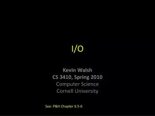
P. M. I/O. Really. P. M. Output. Input. A Disk. Diagram copied from Wikipedia. A. Track. B. Geometrical Sector. C. Sector on one track. D. Sector cluster. time to read/write = seek time + rotational latency + read/write time of sector.

E N D
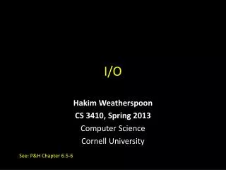
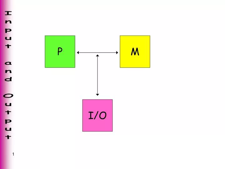
P M I/O
Really. . . P M Output Input
Diagram copiedfromWikipedia A. Track B. Geometrical Sector C. Sector on one track D. Sector cluster
time to read/write = seek time + rotational latency + read/write time of sector
seek time • the time to move the head to the correct track • often presented as an average • usually milliseconds (<10msec)
rotational latency (or delay) • the time it takes for the disk to complete one full rotation • older typical value: 7200 rpm (approx 8 msec)
Consider the implementation of I/O functionality. Who should have access to what, when, for how long, and at what priority? • responsibility • protection • permission • capability • access rights • ownership
End result is that the code that handles all I/O device interactions is in the operating system (OS). • And, the application must be given a way to request that the OS handle I/O. This request is often implemented by introducing an instruction – called syscall on lots of architectures.
What syscall does: • Remember the address within the application of the instruction following the syscall. This is the place to "return" after the I/O operation is completed. • "Jump" to the OS code that handles the I/O operation. Note: this OS code must not overwrite any of the application's register values! • "Return" to the application. This mechanism appears similar to function call and return.
OS code li $2, 12 # getc $8syscallmove $8, $v0 application
P M
How to write the OS code that handles I/O? • The OS must communicate with a large variety of devices. • We could define new instructions input devicenumber rd output devicenumber rs where theinput goes the output
Extra I/O instructions are not a good choice: • there are not enough bits in the machine code to specify everything • cannot properly deal with error conditions So, use the current instruction set.
memory mappingmakes it all work! 0xffff0008 Keyboard_Data 0xffff0010 Display_Data these memory locations aremagicallyattached to devices . . .
2. Keyboard_Data 'X' 1. user types 'X'
1. 'Q' appears in memory 'Q' Display_Data Q 2. character appearson display
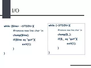
To avoid I/O instructions: • use memory-mapped communication channels • OS code becomes get_c: lw $v0, Keyboard_Data "return" # from syscall put_c: sw $4, Display_Data "return" # from syscall
Problems with this solution: • does not deal with device errors • we want blocking I/O.No "return" until the I/O operation is complete. consider: User runs application, and then talks to a friend. Processor executes greater than a million instructions per second. The application contained a getc syscall. . .
The solution: introduce a status bit for each device • 1 means device ready • 0 means device not ready (also called busy)
There is a trick within this implementation. . . memory map the status bit into its own word. . . 0xffff0008 Keyboard_Data 0xffff000c Keyboard_Status 0xffff0010 Display_Data 0xffff0014 Display_Status use the msb of the status wordas the status bit
Keyboard • ready (status = 1)a character has been typed • not ready (status = 0)no character Display • ready (status = 1)the display may accept a character • busy (status = 0)the display has not yet finished with a previous character. It is not ready for a new one.
Keyboard_Data 'X' 1 Keyboard_Status 2a. 'X' into Keyboard_Data 2b. 1 into Keyboard_Status msb 1. user types 'X'
We can use the status bit in our code: if _Status >= 0 device is not ready if _Status < 0 device is ready
# OS code for getc syscall get_c: lw $k0, Keyboard_Status bgez $k0, get_c lw $v0, Keyboard_Data "return" # from syscall
# OS code for putc syscall put_c: lw $k0, Display_Status bgez $k0, put_c sw $4, Display_Data "return" # from syscall $4 contains the ASCII characterto be printed
spin waiting busy waiting The loop is a spin wait loop.
# application does puts $13 li $v0, 4 move $4, $13 syscall # BAD OS code for puts put_s: lbu $k0, ($4) beqz $k0, exit_puts sw $k0, Display_Data add $4, $4, 1 b put_s exit_puts: "return" # from syscall
# GOOD OS code for puts put_s: lbu $k0, ($4) beqz $k0, exit_puts spin: lw $k1, Display_Status bgez $k1, spin sw $k0, Display_Data add $4, $4, 1 b put_s exit_puts: "return" # from syscall
Summary of Important Concepts • OS handles I/O • syscall instruction invokes the OS • memory mapping avoids the need for separate I/O instructions • the status of a device tells the OS if the device is ready or busy • spin wait loops ensure that input or output occurs once, and synchronize the transfer of data
P M controller
P M Data Keyboard Status Display addresses 0xffff00080xffff000c memory mapped Data Status addresses 0xffff00100xffff0014
a read from Keyboard_Data causes • status bit 0 (not ready) a key press causes • ASCII character code to be placed at Keyboard_Data • status bit 1 (ready)
a write to Display_Data causes • display works on displaying the character in Display_Data • status bit 0 (busy) display completes displaying a character causes • status bit 1 (ready)
This sort of works. . . What if the user types 2 characters before the application does a getc syscall?
A solution ? The OS buffers both input from and output to all devices. Then, the OS must run to check the _Status of each device to see if it is ready. This is called polling.
OS polls keyboard At regular intervals, OS looks at Keyboard_Status. If ready, place character into a queue. head tail 'c' 'b' 'a' OS getc handling dequeues, or (spin) waits until the queue is not empty. . .
Issues: How is the OS code invoked at regular intervals? Whatlength of time is the interval?
Byte transfers are OK, But, what about faster devices that like to transfer more than a byte ? the solution: DMA Direct Memory Access P M controller
DMA transfers occur without processor intervention • set up (writes to special memory mapped locations) • disk address • memory address • number of bytes to transfer • direction of transfer • when is it done ? Status bit for disk becomes ready. So, OS must poll to determine that the DMA transfer has completed.
Keyboard Echo When we type a character on the keyboard, we want to see it on the display. . . Two operations: 1. keyboard input implies 2. display output The OS must implement keyboard echo.
Another Summary of Important Concepts • controllers for devices handle loads and stores to/from their memory mapped locations • pollinghelps with buffering, but has its own problems • DMA works nicely with fast devices